CT90 Clutch Pack Assembly Detail Build-up
All CT90's at some point in their life will have the clutch start to slip and require the clutch assembly to be rebuilt.
Links to Related Posts:
CT90 Engine Reassembly
Making a Low Cost Clutch Holding Tool for Your CT90
Shift Drum Stopper Replacement When Doing a Clutch Rebuild
I have one CT90 where I could tell the clutch was starting to slip because the kickstarter just wasn't turning over the engine like it used too, so I decided to rebuild the clutch. I don't normally tear the whole clutch pack apart when I install new clutch disks, but when I opened up the cases on this bike I found a slick black slime everywhere, so I decided to disassemble the entire clutch assembly (and actually the rest of the engine...) to make sure I cleaned everything out. Since I was tearing everything apart I thought I would document how everything goes back together in this post in case others were interested in knowing what the inner parts of the clutch pack look like.
I have also included a short video at the end to show how the final assembly should lock up if assembled correctly.


As I outline how I go about reassembling the clutch pack assembly, I may not use the official terminology for what each one of the parts may be called by Honda, but you should be able to get an idea of which physical part I am talking about.
To start getting the assembly back together, I first assembly the small lobed weights to the smaller diameter wire ring. These weights are what actually compress the stack of clutch disks as the engine RPM's increase due to the large end of each lobe being driven radially outward due to centrifugal forces. The ring and lobed weights are in the upper left corner in the picture above.
Each lobed weight is slid on to the wire ring in the orientation shown in the picture below.


The next step is to install the ring with the lobed weights into the machined steel casting that is the primary element that ties the overall clutch assembly together. Set the ring with the lobed weights on the machined part as shown in the picture below lining up the bent end of the ring with the corresponding hole shown in the upper right corner of the picture below. Also line up each group of six lobe weights with the corresponding machined slots.

You next install the ring in the mating groove by first installing the bent end of the ring in the hole and then work your way around inserting the ring as you go until it is all the way seated in the groove. The picture below shows the ring about three quarters of the way installed in the groove.

The next step is to install the larger diameter ring buy first flipping the previous built assembly over and then install the larger diameter ring in the groove that runs around the circumference of the machined part. Once you are complete it should look like the picture below and the key thing is to make sure the bent end of the ring is located in the mating detent of the machined part that is identified in the picture below.

The next step is to install the four springs shown in the picture below.

You install each spring over the posts that have a threaded hole at their center as shown below.

With the springs in place take the clutch basket and set it on top of the assembly taking care to line up the holes in the clutch basket that have the shallow counterbore with the posts that have the springs installed. It helps in this and the next step to have placed a small block of wood under the center of the assembly to help lift it off the bench.

When you place the clutch basket on the assembly with the springs you may need to use a small screw driver or some other object to make sure the springs are seated in their respective counterbores.
Once the clutch basket is correctly located I just press down on the basket until I can get each of the four screws and washers started into each of the threaded holes at the center of the four posts. Once all four screws are started, I continue tightening the screws progressively in a criss cross pattern until they are fully seated and tight. An option is to apply a little blue Loctite to each of these screws to help ensure they don't come lose sometime in the future.
The next step is to install the four springs that go between the clutch basket and the four posts that have a mating hole for the spring drilled into the side of each post.

To install each spring I insert one end of the spring in the hole on the post and then use a small screwdriver to compress the spring and slip it over the small post that is part of the clutch basket and then repeat this process for each spring.

The picture below shows a correctly installed spring.


The next step is to assembly what I'll call the drive gear assembly that is made up of the parts shown in the picture below.

The assembly is pretty straight forward and involves threading the drive gear into the splined center section and then these two parts are held together with the large flat retaining ring.

When I assemble these parts I'll thread the drive gear into the splined center section and then place those two parts on something like the piston I am using in the picture above. This makes it easier to install the retaining ring because it keeps the groove accessible.
The retaining ring is pretty stiff and I'll use a combination of threading it into the groove combined with snap ring pliers or whatever else is required to get it into the groove as shown in the pictures below.


With these two assemblies complete we can start the final assembly of the overall clutch assembly. This is where you would start if you were just replacing worn out clutch disks.

The next step would be to place the drive gear assembly into the clutch basket assembly.

The final part of the assembly process is to layer in the disks and plates that make up that actual clutch pack. The picture below shows all the parts that will be assembled. I have taken emory cloth (using 1000 grit or so) and lightly scuffed up the surface of each plate that comes into contact with a disk to break any glaze present on the surface. If you do this, go easy as you really don't want to roughen up the surface.
You may have noticed that this group of parts has four long springs and two short springs. I have done clutches on CT90's that only have the four longer springs and the number of springs varied between different years of CT90's, so while the two short springs are nice to have they are not critical, but they do help keep the plates separated when the clutch is disengaged.

Before I assemble everything into the clutch basket I thought I would show a series of pictures assembling the disks and plates on the bench so that it is easier to see how everything comes together.
The first step is to install the six springs on the plate that has the six attached posts as shown below.

Next a clutch disk is added

And then the plate that has no holes is added as the slots on the plates will clear all six springs.

Another disk is added.

And then the plate with four holes and four slots is added with two of the tabs that have holes being placed on top of the two shorter springs.

The last disk is added.

And the final step is to add the plate that only has holes on each of the tabs.

Before we get back to assembling the plates and disks into the clutch basket assembly, I wanted to share one detail that I look at when assembling the first plate that has the six pins for the springs.
If you look at the picture below you'll see that the side of the plate opposite of the pins has gouges or witness marks from contact with the lobed weights that compress the clutch pack in use.

When I see these marks I'll generally rotate the plate one position when I install it so that these marks don't line up with the lobed weights and the lobed weights now will be in contact with a clean undisturbed surface of the plate. I don't know if it really makes much difference in the operation of the clutch, but its something I do as it get the interface between those parts like it would be with a new part. Another option would be to take some emery cloth and smooth over the gouges or witness marks.
So getting back to completing the assembly, drop the plate that has the six pins into the clutch basket assembly.

Next install the four longer springs one the outer posts and then the two shorter springs (if used) on the two opposing post between the other posts you installed the longer springs on. In the end it should look like the picture below.

Next drop in the first clutch disk with the spines on the inside diameter engaging the mating splines on the clutch pack assembly.

Next drop in the plate that has no holes and only slots and make sure it has not hung up on any of the springs.

Next drop in the second clutch disk agin making sure the splines on the inside diameter engage the mating splines on the clutch pack assembly.

Next drop in the plate the has four holes and four slots making sure the tabs with holes are placed over the two shorter springs.

Next drop in the final clutch disk again making sure the splines on the inside diameter engage with the splines on the clutch pack assembly.

Next take the last plate that only has holes in the tabs and set it on the assembly so the that holes in the tabs line up with the six pins.

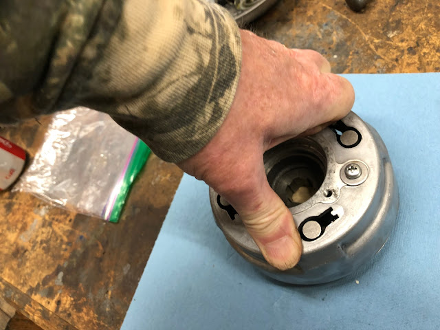
Next we will install the large diameter flat retaining ring that has one bent end. This is the final part to be installed and holds the clutch pack together

I start by installing the bent end of the ring in one of the slots the tabs from the last plate were installed into. You first need to compress the plate until the groove is exposed that the retaining ring will mate into and then slide the retaining ring into the groove.

You continue that process working your way around the clutch pack.

Once you are complete it should look like the picture below.

At this point you are done with the assembly process and its time to do a quick and simple test.
I figured the simplest way to explain the test is to just include a short video below showing and describing the test to verify that your clutch pack assembly was assembled correctly.
After you get your clutch pack installed back in your engine, here is a video on how to adjust your clutch.
I hope this post provides you with helpful information to support your next CT90 clutch pack rebuild.
Links to Related Posts:
CT90 Engine Reassembly
Making a Low Cost Clutch Holding Tool for Your CT90
Shift Drum Stopper Replacement When Doing a Clutch Rebuild
Helpful Links (Shop Manuals, Wire Diagram, Model Information, etc.)
Link to page with listing of CT90 parts available on Amazon
Links to Related Posts:
CT90 Engine Reassembly
Making a Low Cost Clutch Holding Tool for Your CT90
Shift Drum Stopper Replacement When Doing a Clutch Rebuild
I have one CT90 where I could tell the clutch was starting to slip because the kickstarter just wasn't turning over the engine like it used too, so I decided to rebuild the clutch. I don't normally tear the whole clutch pack apart when I install new clutch disks, but when I opened up the cases on this bike I found a slick black slime everywhere, so I decided to disassemble the entire clutch assembly (and actually the rest of the engine...) to make sure I cleaned everything out. Since I was tearing everything apart I thought I would document how everything goes back together in this post in case others were interested in knowing what the inner parts of the clutch pack look like.
I have also included a short video at the end to show how the final assembly should lock up if assembled correctly.

Here is a picture of all the parts that make up the clutch assembly on my 1971 CT90. I have already cleaned up all the detail parts and let my new clutch disks soak overnight in oil, so everything is ready to be assembled.

As I outline how I go about reassembling the clutch pack assembly, I may not use the official terminology for what each one of the parts may be called by Honda, but you should be able to get an idea of which physical part I am talking about.
To start getting the assembly back together, I first assembly the small lobed weights to the smaller diameter wire ring. These weights are what actually compress the stack of clutch disks as the engine RPM's increase due to the large end of each lobe being driven radially outward due to centrifugal forces. The ring and lobed weights are in the upper left corner in the picture above.
Each lobed weight is slid on to the wire ring in the orientation shown in the picture below.

There are twenty four lobed weights and once they are all on the ring you separate them into four groups of six.

The next step is to install the ring with the lobed weights into the machined steel casting that is the primary element that ties the overall clutch assembly together. Set the ring with the lobed weights on the machined part as shown in the picture below lining up the bent end of the ring with the corresponding hole shown in the upper right corner of the picture below. Also line up each group of six lobe weights with the corresponding machined slots.

You next install the ring in the mating groove by first installing the bent end of the ring in the hole and then work your way around inserting the ring as you go until it is all the way seated in the groove. The picture below shows the ring about three quarters of the way installed in the groove.

The next step is to install the larger diameter ring buy first flipping the previous built assembly over and then install the larger diameter ring in the groove that runs around the circumference of the machined part. Once you are complete it should look like the picture below and the key thing is to make sure the bent end of the ring is located in the mating detent of the machined part that is identified in the picture below.

The next step is to install the four springs shown in the picture below.

You install each spring over the posts that have a threaded hole at their center as shown below.

With the springs in place take the clutch basket and set it on top of the assembly taking care to line up the holes in the clutch basket that have the shallow counterbore with the posts that have the springs installed. It helps in this and the next step to have placed a small block of wood under the center of the assembly to help lift it off the bench.

When you place the clutch basket on the assembly with the springs you may need to use a small screw driver or some other object to make sure the springs are seated in their respective counterbores.

Once the clutch basket is correctly located I just press down on the basket until I can get each of the four screws and washers started into each of the threaded holes at the center of the four posts. Once all four screws are started, I continue tightening the screws progressively in a criss cross pattern until they are fully seated and tight. An option is to apply a little blue Loctite to each of these screws to help ensure they don't come lose sometime in the future.
The next step is to install the four springs that go between the clutch basket and the four posts that have a mating hole for the spring drilled into the side of each post.

To install each spring I insert one end of the spring in the hole on the post and then use a small screwdriver to compress the spring and slip it over the small post that is part of the clutch basket and then repeat this process for each spring.

The picture below shows a correctly installed spring.


The next step is to assembly what I'll call the drive gear assembly that is made up of the parts shown in the picture below.

The assembly is pretty straight forward and involves threading the drive gear into the splined center section and then these two parts are held together with the large flat retaining ring.

When I assemble these parts I'll thread the drive gear into the splined center section and then place those two parts on something like the piston I am using in the picture above. This makes it easier to install the retaining ring because it keeps the groove accessible.
The retaining ring is pretty stiff and I'll use a combination of threading it into the groove combined with snap ring pliers or whatever else is required to get it into the groove as shown in the pictures below.


With these two assemblies complete we can start the final assembly of the overall clutch assembly. This is where you would start if you were just replacing worn out clutch disks.


The final part of the assembly process is to layer in the disks and plates that make up that actual clutch pack. The picture below shows all the parts that will be assembled. I have taken emory cloth (using 1000 grit or so) and lightly scuffed up the surface of each plate that comes into contact with a disk to break any glaze present on the surface. If you do this, go easy as you really don't want to roughen up the surface.
You may have noticed that this group of parts has four long springs and two short springs. I have done clutches on CT90's that only have the four longer springs and the number of springs varied between different years of CT90's, so while the two short springs are nice to have they are not critical, but they do help keep the plates separated when the clutch is disengaged.

Before I assemble everything into the clutch basket I thought I would show a series of pictures assembling the disks and plates on the bench so that it is easier to see how everything comes together.
The first step is to install the six springs on the plate that has the six attached posts as shown below.

Next a clutch disk is added

And then the plate that has no holes is added as the slots on the plates will clear all six springs.

Another disk is added.

And then the plate with four holes and four slots is added with two of the tabs that have holes being placed on top of the two shorter springs.

The last disk is added.

And the final step is to add the plate that only has holes on each of the tabs.

Before we get back to assembling the plates and disks into the clutch basket assembly, I wanted to share one detail that I look at when assembling the first plate that has the six pins for the springs.
If you look at the picture below you'll see that the side of the plate opposite of the pins has gouges or witness marks from contact with the lobed weights that compress the clutch pack in use.

When I see these marks I'll generally rotate the plate one position when I install it so that these marks don't line up with the lobed weights and the lobed weights now will be in contact with a clean undisturbed surface of the plate. I don't know if it really makes much difference in the operation of the clutch, but its something I do as it get the interface between those parts like it would be with a new part. Another option would be to take some emery cloth and smooth over the gouges or witness marks.
So getting back to completing the assembly, drop the plate that has the six pins into the clutch basket assembly.

Next install the four longer springs one the outer posts and then the two shorter springs (if used) on the two opposing post between the other posts you installed the longer springs on. In the end it should look like the picture below.

Next drop in the first clutch disk with the spines on the inside diameter engaging the mating splines on the clutch pack assembly.

Next drop in the plate that has no holes and only slots and make sure it has not hung up on any of the springs.

Next drop in the second clutch disk agin making sure the splines on the inside diameter engage the mating splines on the clutch pack assembly.

Next drop in the plate the has four holes and four slots making sure the tabs with holes are placed over the two shorter springs.

Next drop in the final clutch disk again making sure the splines on the inside diameter engage with the splines on the clutch pack assembly.

Next take the last plate that only has holes in the tabs and set it on the assembly so the that holes in the tabs line up with the six pins.

Next we will install the large diameter flat retaining ring that has one bent end. This is the final part to be installed and holds the clutch pack together

I start by installing the bent end of the ring in one of the slots the tabs from the last plate were installed into. You first need to compress the plate until the groove is exposed that the retaining ring will mate into and then slide the retaining ring into the groove.

You continue that process working your way around the clutch pack.

Once you are complete it should look like the picture below.

At this point you are done with the assembly process and its time to do a quick and simple test.
I figured the simplest way to explain the test is to just include a short video below showing and describing the test to verify that your clutch pack assembly was assembled correctly.
After you get your clutch pack installed back in your engine, here is a video on how to adjust your clutch.
I hope this post provides you with helpful information to support your next CT90 clutch pack rebuild.
Links to Related Posts:
CT90 Engine Reassembly
Making a Low Cost Clutch Holding Tool for Your CT90
Shift Drum Stopper Replacement When Doing a Clutch Rebuild
Helpful Links (Shop Manuals, Wire Diagram, Model Information, etc.)
Link to page with listing of CT90 parts available on Amazon
Thank you thank you outstanding!
ReplyDelete