Building a basic Honda CT90 static timing light from a free Harbor Freight LED light
If you ever plan on setting the timing on your CT90, one of the tools you will need is a static timing light. You can go out and buy a simple static timing lights as there are several available, but they are actually very easy to make yourself from just about any small hand held LED light that seem to be readily available everywhere.
If you are going to adjust the timing on your Honda CT90 I made a post here with step by step instructions on the process you need to follow.
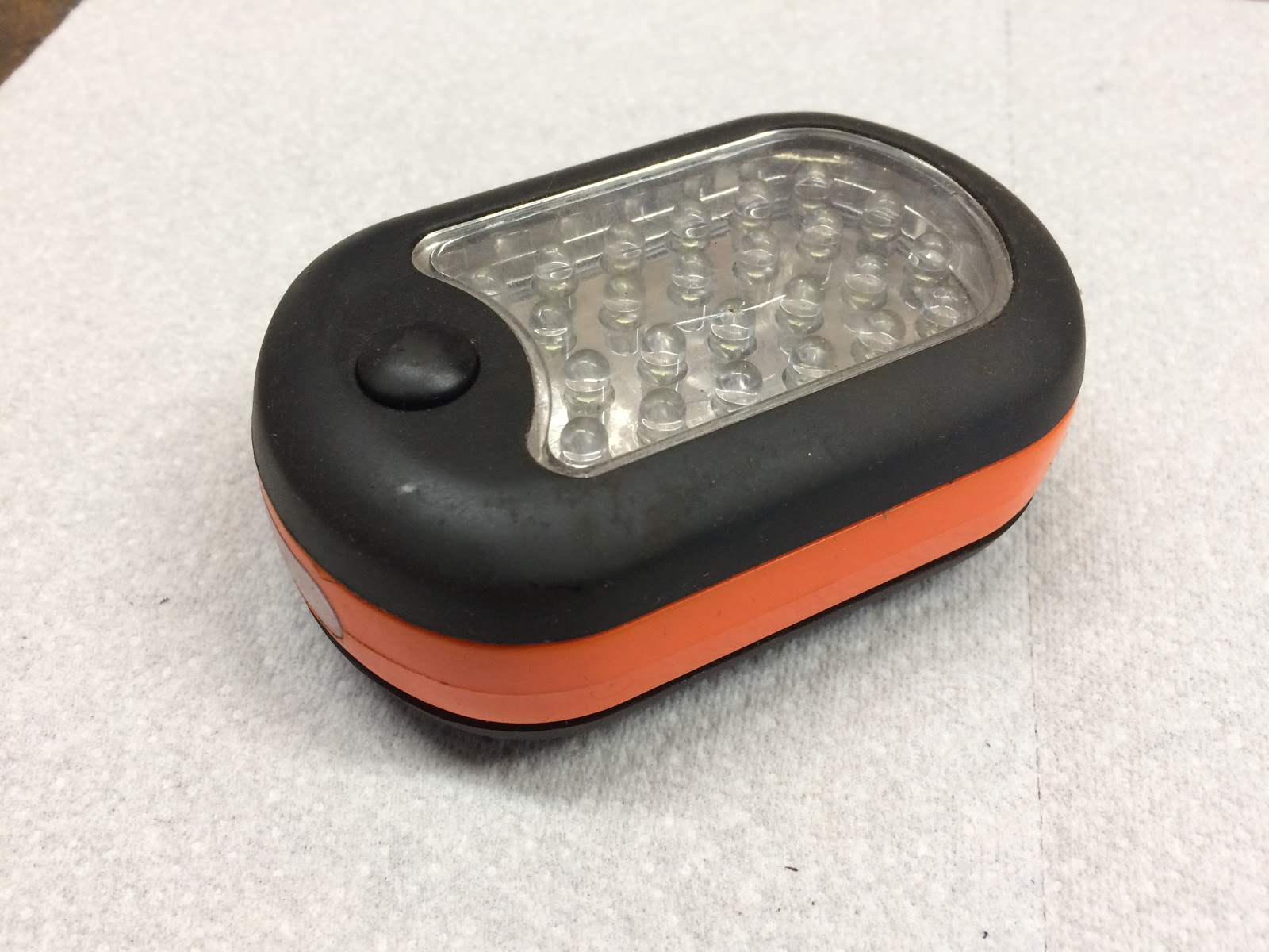
If your in a part of the world that has Harbor Freight and you get the mailers from them on a regular basis, you'll already know that they offer a number of free items with a purchase, and one of those free items is a LED work light/flashlight that is Item # 60566, which by the way also is a great light to modify into a static timing light for your CT90.
I have a number of these lights in my shop as they are cheap/free, provide good light and also have a hook and magnet which come on handy when you're using the light.

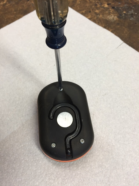
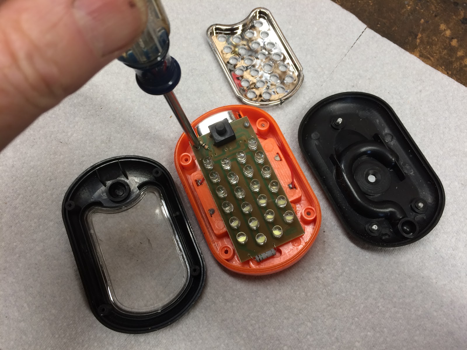
To start the modification process you'll need to disassemble the light by first removing the three screws on the backside of the case.
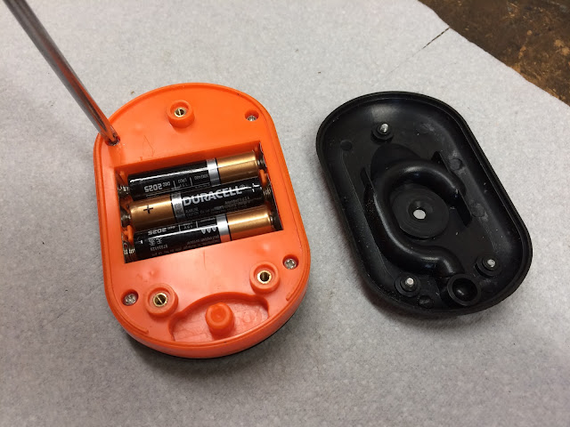
Once you have the back of the light removed, you next need to remove the three batteries and then the four screws that hold on the front faceplate of the light.
With the four screws removed, you next need to flip the light over and set the top cover aside.
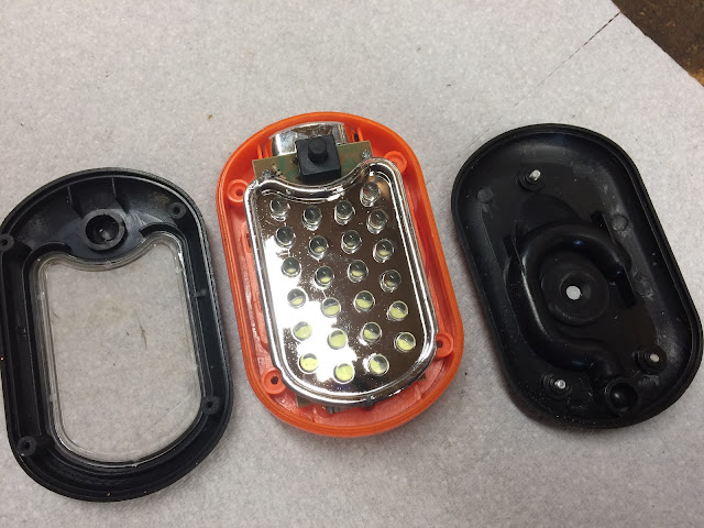
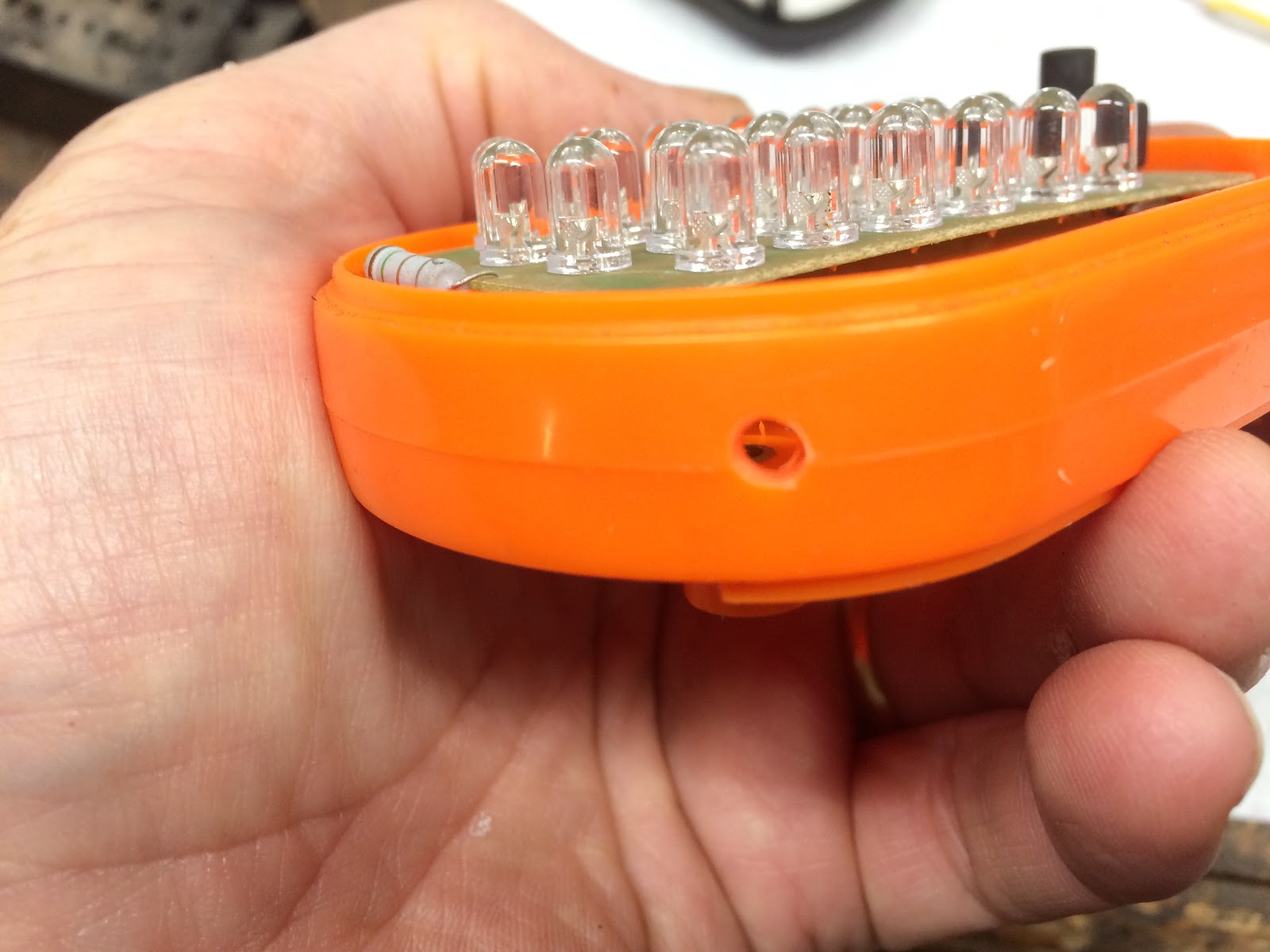
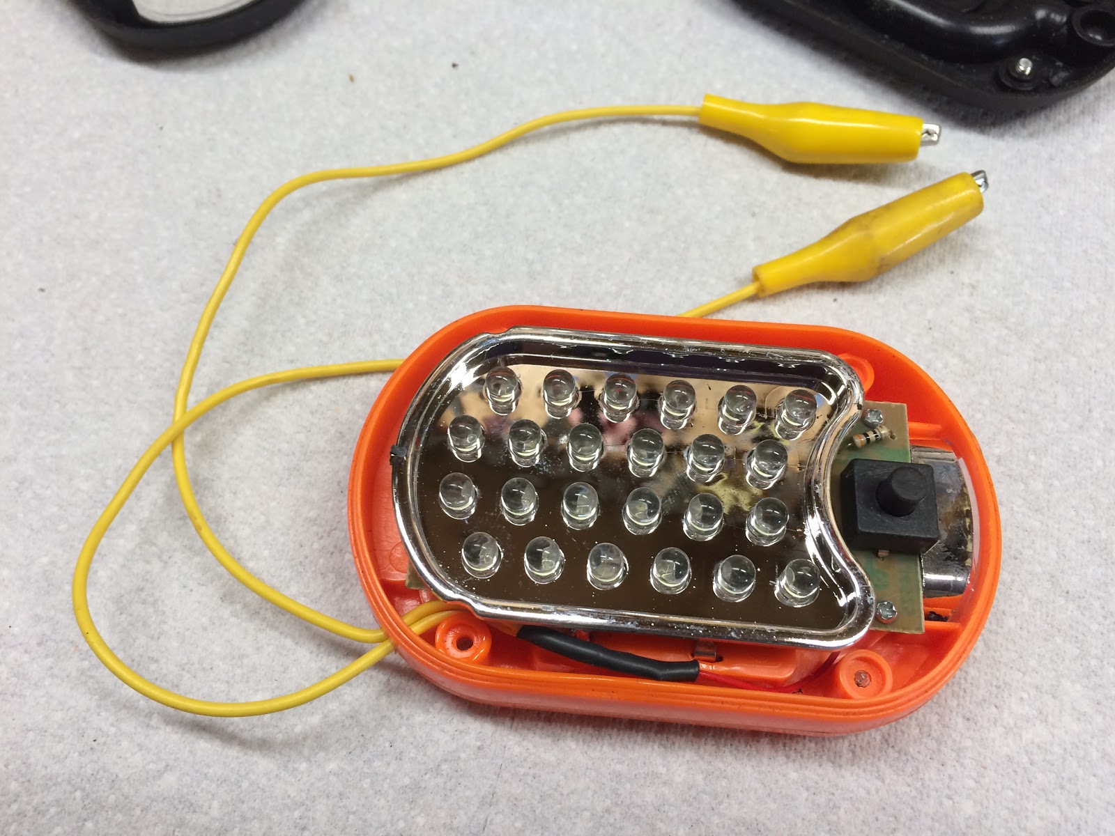
Next, the shinny plate that is just slipped over the 24 LED's of the main light can be removed and set to the side. This will expose the main circuit board that is held in place by two small screws located near the on/off button, which need to be removed.

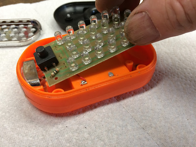
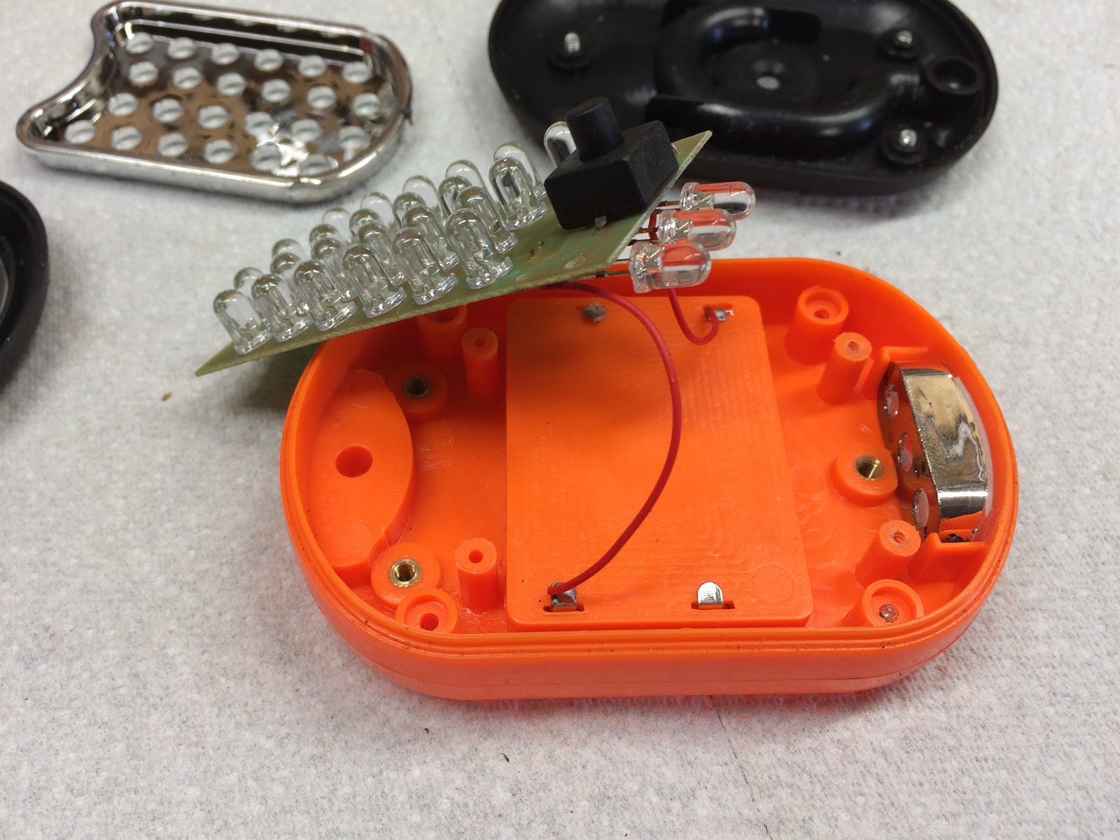
Once the two screws are removed, the next step is to partially remove the circuit board by sliding it back and up from the end of the light that contains three LED's so that the board is loose, but still attached by the two wires going to the batteries.

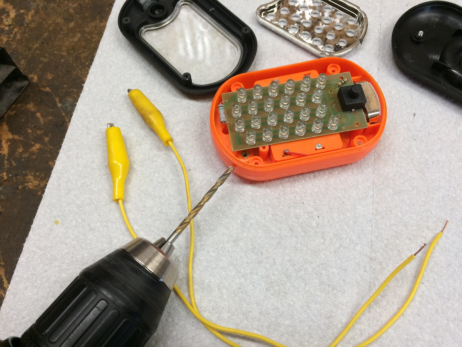
For the wire leads of the timing light, I just use a jumper assembly that has two alligator clips already attached. The jumpers assemblies are cheap and also available at Harbor Freight and are called Low Voltage Test Leads and are also a handy thing to have in your shop if you already don't own them.
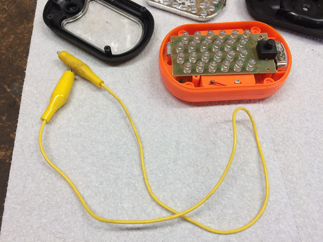
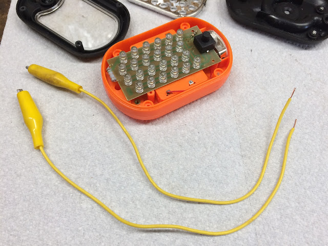
I cut the jumper in half and then strip a small amount of insulation from each wire that is needed for when we install and solder the wires later in the process.
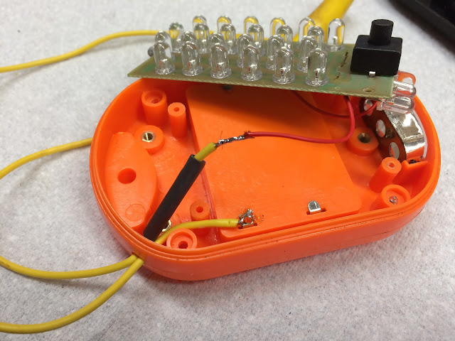
The next step in the modification of the light is to drill a hole that is just large enough for the two wire leads to squeeze through in the corner of the housing opposite the on/off button and near the one wire coming from the battery compartment. The snug fit between the hole and the wires will help prevent the wires from tugging on the solder joints that are the next step in the modification.

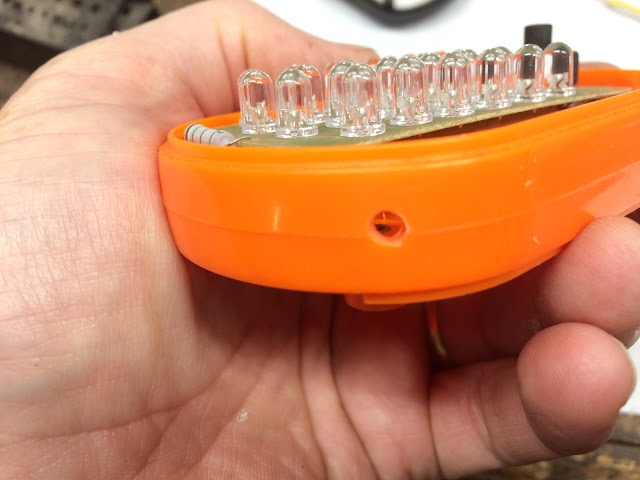
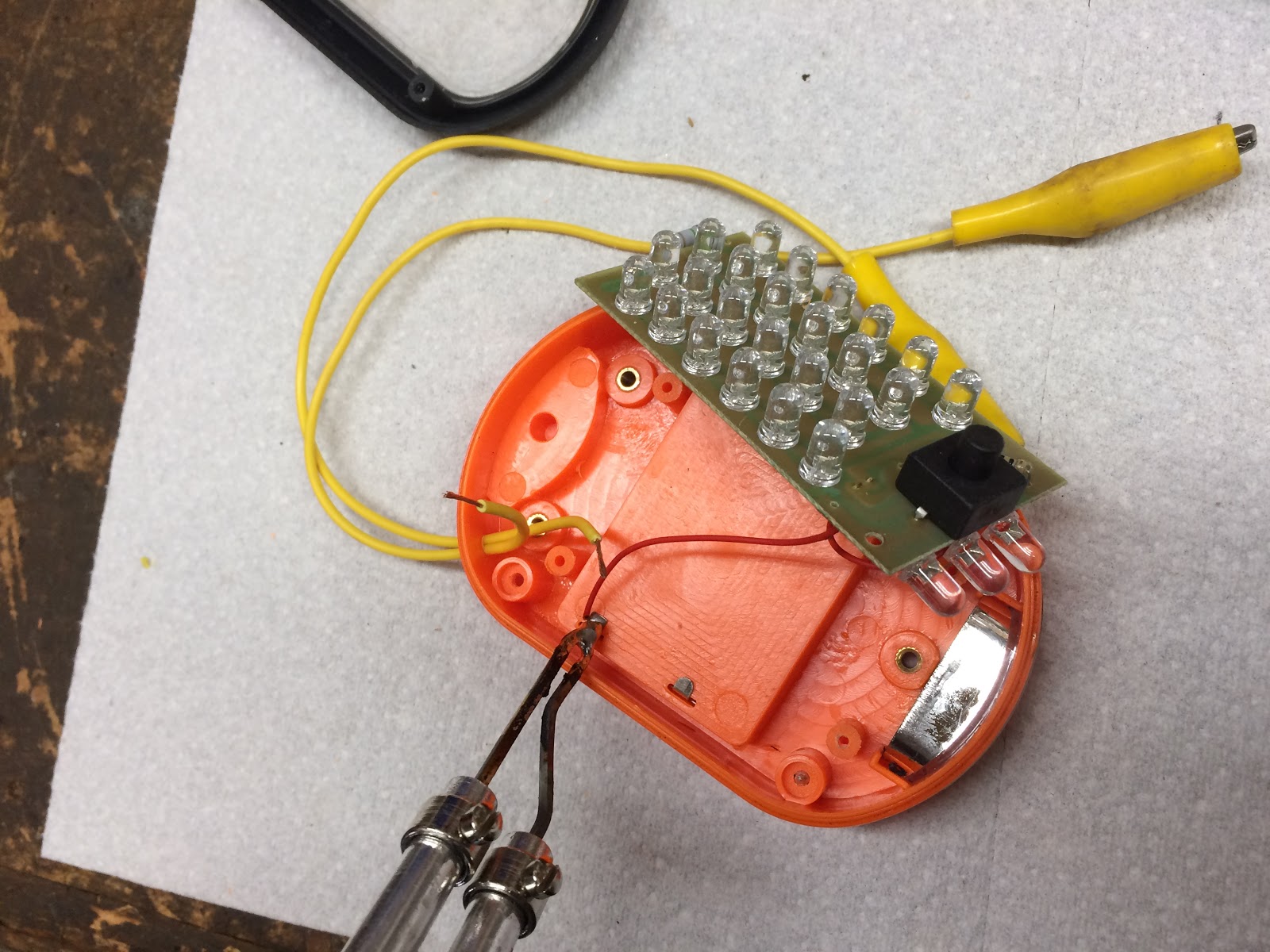
Next feed the two wires through the hole you just made.
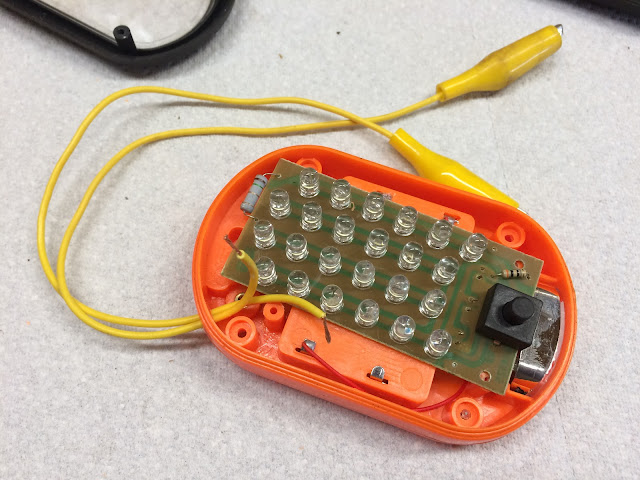
With a soldering iron unsolder the one red wire from the battery compartment and then solder one of the leads with an alligator clip to the battery compartment point that you just removed the red wire from.

Next slip a short section of heat shrink tubing over the remaining lead and then solder that lead to the end of the red wire you unsoldered in the last step.
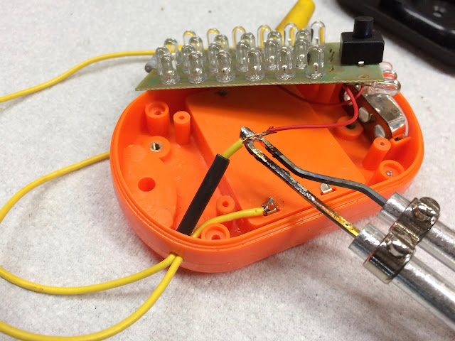
Next slip the heat shrink tubing back over the joint you just soldered and apply heat to shrink the tubing. If you don't have heat shrink tubing its ok to use tape to protect this joint.
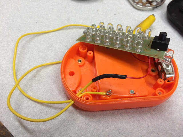
With the last step complete, now you just need to reassemble the light, reversing the process I outlined at the beginning of the modification process above.

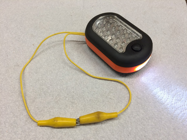
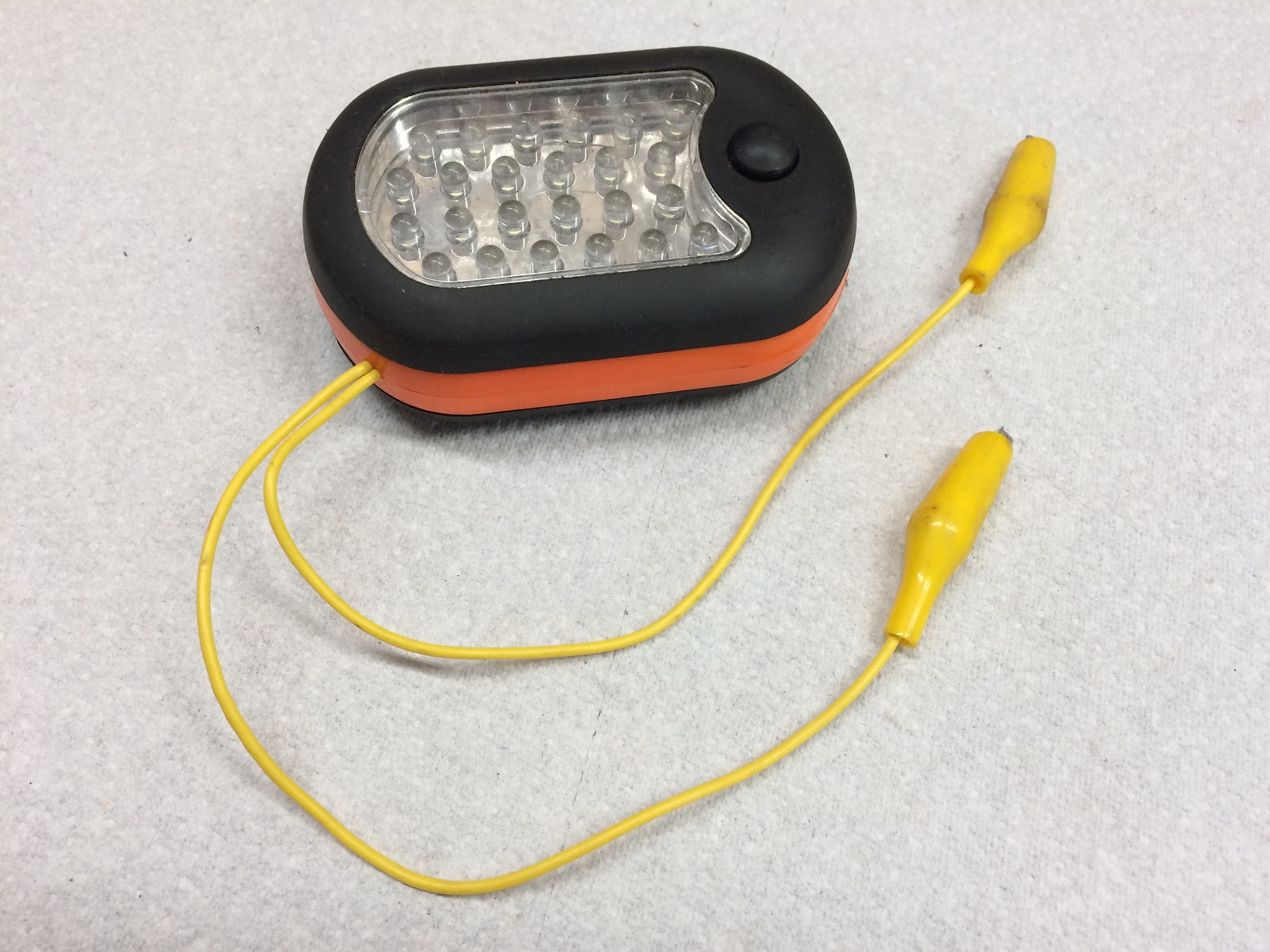
Your CT90 static timing light is now complete.

It's best to keep the two alligator clips clipped to each other so that the light can function normally and when you need to use it as a static timing light, first keep the clips connected together to verify that the light is on, then disconnect them and hook the static timing light up to your CT90 to set your timing.
I plan on writing another blog in the very near future to detail out the steps to adjust your timing using this static timing light, so stay tuned.
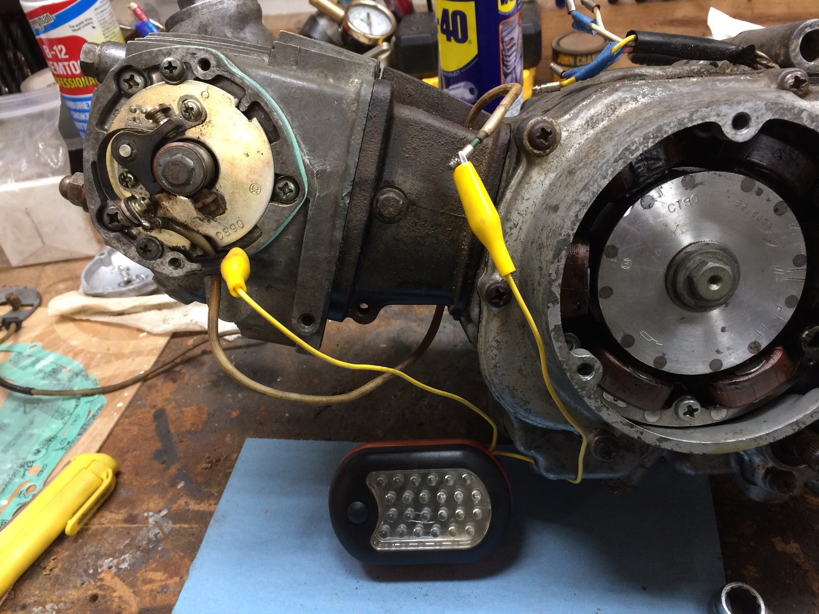
The picture below shows an example on how you would attach the static timing light by connecting one lead to the end of the wire coming from the points and the other lead clipped to the housing.

I have also attached the video below to show you what will happen when you have this static timing light hooked up to a CT90 where the timing is adjusted correctly and the rotor on the engine is rotated counter clockwise past the "F" indicator mark.
I hope this was helpful to anyone looking to set the timing on their CT90 by using a static timing light built using the instructions above.
Related Posts:
The Basic sequence and Process to Set or Adjust Your CT90 Timing
CT90 Engine Reassembly
Helpful Links (Shop Manuals, Wire Diagram, Model Information, etc.)
Link to page with listing of CT90 parts available on Amazon
If you are going to adjust the timing on your Honda CT90 I made a post here with step by step instructions on the process you need to follow.
If your in a part of the world that has Harbor Freight and you get the mailers from them on a regular basis, you'll already know that they offer a number of free items with a purchase, and one of those free items is a LED work light/flashlight that is Item # 60566, which by the way also is a great light to modify into a static timing light for your CT90.
I have a number of these lights in my shop as they are cheap/free, provide good light and also have a hook and magnet which come on handy when you're using the light.
To start the modification process you'll need to disassemble the light by first removing the three screws on the backside of the case.

Once you have the back of the light removed, you next need to remove the three batteries and then the four screws that hold on the front faceplate of the light.

With the four screws removed, you next need to flip the light over and set the top cover aside.

Next, the shinny plate that is just slipped over the 24 LED's of the main light can be removed and set to the side. This will expose the main circuit board that is held in place by two small screws located near the on/off button, which need to be removed.
Once the two screws are removed, the next step is to partially remove the circuit board by sliding it back and up from the end of the light that contains three LED's so that the board is loose, but still attached by the two wires going to the batteries.

For the wire leads of the timing light, I just use a jumper assembly that has two alligator clips already attached. The jumpers assemblies are cheap and also available at Harbor Freight and are called Low Voltage Test Leads and are also a handy thing to have in your shop if you already don't own them.

I cut the jumper in half and then strip a small amount of insulation from each wire that is needed for when we install and solder the wires later in the process.

The next step in the modification of the light is to drill a hole that is just large enough for the two wire leads to squeeze through in the corner of the housing opposite the on/off button and near the one wire coming from the battery compartment. The snug fit between the hole and the wires will help prevent the wires from tugging on the solder joints that are the next step in the modification.
Next feed the two wires through the hole you just made.

With a soldering iron unsolder the one red wire from the battery compartment and then solder one of the leads with an alligator clip to the battery compartment point that you just removed the red wire from.
Next slip a short section of heat shrink tubing over the remaining lead and then solder that lead to the end of the red wire you unsoldered in the last step.


Next slip the heat shrink tubing back over the joint you just soldered and apply heat to shrink the tubing. If you don't have heat shrink tubing its ok to use tape to protect this joint.

With the last step complete, now you just need to reassemble the light, reversing the process I outlined at the beginning of the modification process above.
Your CT90 static timing light is now complete.
It's best to keep the two alligator clips clipped to each other so that the light can function normally and when you need to use it as a static timing light, first keep the clips connected together to verify that the light is on, then disconnect them and hook the static timing light up to your CT90 to set your timing.

I plan on writing another blog in the very near future to detail out the steps to adjust your timing using this static timing light, so stay tuned.
The picture below shows an example on how you would attach the static timing light by connecting one lead to the end of the wire coming from the points and the other lead clipped to the housing.
I have also attached the video below to show you what will happen when you have this static timing light hooked up to a CT90 where the timing is adjusted correctly and the rotor on the engine is rotated counter clockwise past the "F" indicator mark.
I hope this was helpful to anyone looking to set the timing on their CT90 by using a static timing light built using the instructions above.
Related Posts:
The Basic sequence and Process to Set or Adjust Your CT90 Timing
CT90 Engine Reassembly
Helpful Links (Shop Manuals, Wire Diagram, Model Information, etc.)
Link to page with listing of CT90 parts available on Amazon
Comments
Post a Comment