How to Test Your CT90 Condenser
One item often overlooked on a CT90 when trouble shooting is the condenser that is mounted with the ignition coil. The primary function of the condenser is to prevent arcing at the ignition points when the points open which results in a spark being generated at the spark plug. The condenser also to a lessor degree, helps maintain the spark at the spark plug.
Links to Related Posts
CT90 Rectifier Upgrade
Basic CT90 Ignition Coil Check
How to Test Your CT90 Rectifier
Unlike CT90 ignition coils which can be 50 years old and still be in great shape, a condenser is really just a capacitor and capacitors can and will degrade with time, so its always worthwhile to take the time to test the condenser, especially if you have gone to the trouble to remove the coil/condenser assembly from your CT90.
There are a couple of different ways you can check your condenser to determine if it is performing correctly.
The first approach is to make a couple of subjective observations on your CT90. The most basic check is to look at the color of the spark being generated at your spark plug. If the spark is not bright blue and has a more yellowish orange color then that could be an indication that your condenser is not performing adequately. The next subjective check is to pull the cover on the cylinder head of your CT90 so that you can observe and see if there is any arcing going on at the gap in your points while your engine is running like is shown in the video at this link. If you see arcing like is shown in the video then you should replace your condenser.
The second and most direct method to check your condenser is to use a digital voltmeter that has the capability to test capacitors or a capacitor tester like the one at this link at Amazon. If you use an actual capacitor meter you would be looking for a reading of 0.22 to 0.33 uF (micro Farads).
The last method is to use a digital voltmeter that has the capability to measure resistance and DC voltage. This is the method I will be outlining in more detail below as most people generally have access to a basic digital voltmeter. This method is not as direct as using a capacitor meter, but it will give you a good indication if your condenser if performing correctly.
Here are some links to related posts:
How to Test Your CT90 Rectifier
Basic CT90 Ignition Coil Check
CT90 Rectifier Upgrade
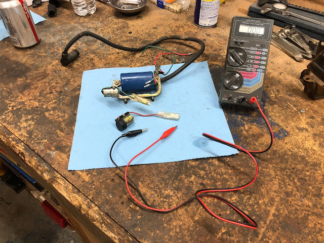
The first step in checking your condenser is to set up your digital voltmeter to read low DC voltage and with the digital voltmeter I have I set the range knob to 3 volts DC. You then will connect the positive lead (red in the picture below) to the lead coming off of the condenser and then connect the negative lead (black in the picture below) to the case of the condenser making sure you are insulated from the negative lead if you are holding in with your hand.
What you should see if there is any residual charge in your condenser is that the voltage reading being displayed will be decreasing and at some point should go to zero. What is happing during this step of the test is that the digital voltmeter is putting a load on the condenser as part of its effort to measure voltage, but the load being applied will discharge the condenser if it is working correctly. If you got an initial reading of zero during this portion of the test that is ok as what we are trying to do is just get the condenser in a known state before we run the actual test.
for the next step of the test make sure the negative lead is disconnected from the condenser.
Change the settings on your digital voltmeter to measure very high resistance. On the digital voltmeter I am using I set it to the maximum range settings available.
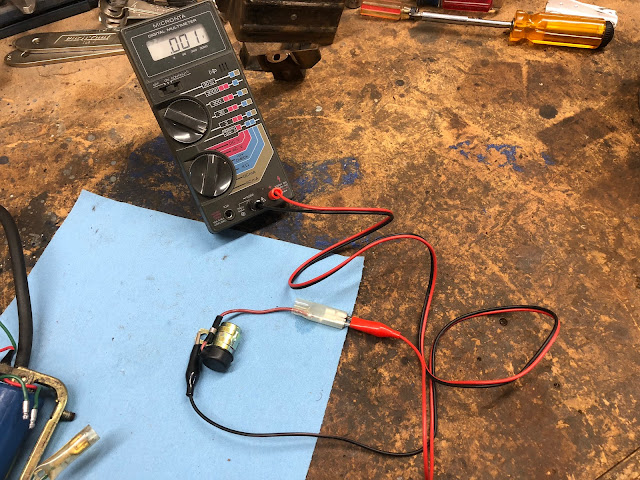
Next touch and hold or connect the negative lead to the case of the condenser making sure you are not in contact with the negative lead as shown in the picture below.
What will happen during this phase of the test is that you should see the reading on the digital voltmeter increase until it indicates that it is at a maximum value or out of range. The value being displayed is not what is important, but it does need to increase until it is out of range. Continue to keep the lead in contact with the case for at least 15 to 20 seconds. What is happening is this phase of the test is that the digital voltmeter is passing a current through the condenser which has the effect of charging up the condenser which is what we are trying to check. If all is good with your condenser it was charged up during during this phase of the test.
Next, disconnect the negative lead and reset your digital voltmeter back to measure small DC voltage like what was done during the first step performed earlier. After you have reset the digital voltmeter do not yet connect the negative lead to the condenser.
Take a little break before proceeding as what we want to check in the next step is if your condenser was able to hold the charge you built up in it during the last step in the test.
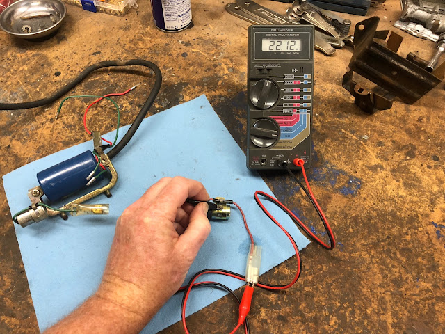
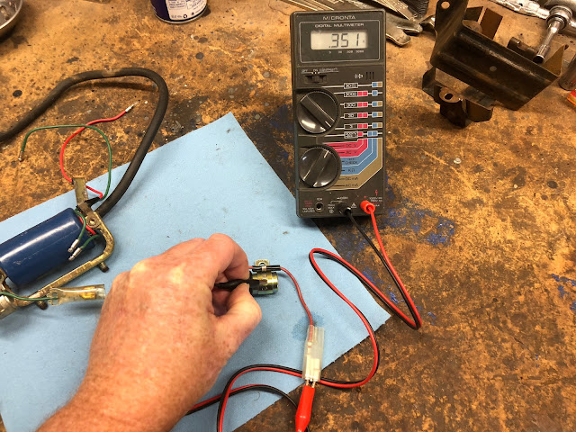
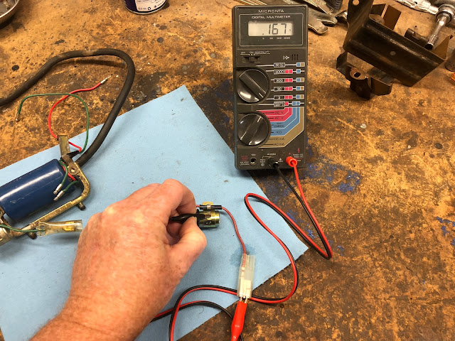
Once some time has passed now take the negative lead and touch it to the case of the condenser for just a second or two and what you should see is a nominal voltage that started to decrease until you removed the negative lead. Remember the approximate value being displayed at the time you remove the lead. For the condenser I was testing below the initial valve was slightly greater then the 0.351 volts being displayed below.
And when I removed the negative lead the reading was 0.167 volts.
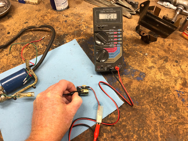
Once some time has passed (20 seconds or greater) retouch the negative lead to the case and now the value on the display should be close but slightly less then the previous value. For the example in the picture below the valve when I retouched the negative lead was 0.151 volts.
Continue to hold the negative lead to the case of the condenser and the value being displayed on the digital voltmeter should decrease all the way back to zero.
Again what we are trying to verify with this series of tests is that the condenser:
1. Can be charged up
2. Can hold the charge for some period of time
3. Can be discharged
If using the test I outlined above you verified that your condenser could do each of the three items I just listed above then your condenser should be good.
I also did a short video below to walk thru the whole process on how to check your CT90 condenser.
If you do find you need a new condenser for your CT90 you can check out the following links:
CT90 Condenser at Amazon
CT90 Condenser at DrATV/Beatrice
I hope this post is helpful in resolving any issues you may be having with your CT90 condenser.
Links to Related Posts
CT90 Rectifier Upgrade
Basic CT90 Ignition Coil Check
How to Test Your CT90 Rectifier
Helpful Links (Shop Manuals, Wire Diagram, Model Information, etc.)
Link to page with listing of CT90 parts available on Amazon
Links to Related Posts
CT90 Rectifier Upgrade
Basic CT90 Ignition Coil Check
How to Test Your CT90 Rectifier
Unlike CT90 ignition coils which can be 50 years old and still be in great shape, a condenser is really just a capacitor and capacitors can and will degrade with time, so its always worthwhile to take the time to test the condenser, especially if you have gone to the trouble to remove the coil/condenser assembly from your CT90.
There are a couple of different ways you can check your condenser to determine if it is performing correctly.
The first approach is to make a couple of subjective observations on your CT90. The most basic check is to look at the color of the spark being generated at your spark plug. If the spark is not bright blue and has a more yellowish orange color then that could be an indication that your condenser is not performing adequately. The next subjective check is to pull the cover on the cylinder head of your CT90 so that you can observe and see if there is any arcing going on at the gap in your points while your engine is running like is shown in the video at this link. If you see arcing like is shown in the video then you should replace your condenser.
The second and most direct method to check your condenser is to use a digital voltmeter that has the capability to test capacitors or a capacitor tester like the one at this link at Amazon. If you use an actual capacitor meter you would be looking for a reading of 0.22 to 0.33 uF (micro Farads).
The last method is to use a digital voltmeter that has the capability to measure resistance and DC voltage. This is the method I will be outlining in more detail below as most people generally have access to a basic digital voltmeter. This method is not as direct as using a capacitor meter, but it will give you a good indication if your condenser if performing correctly.
Here are some links to related posts:
How to Test Your CT90 Rectifier
Basic CT90 Ignition Coil Check
CT90 Rectifier Upgrade
The first step in checking your condenser is to set up your digital voltmeter to read low DC voltage and with the digital voltmeter I have I set the range knob to 3 volts DC. You then will connect the positive lead (red in the picture below) to the lead coming off of the condenser and then connect the negative lead (black in the picture below) to the case of the condenser making sure you are insulated from the negative lead if you are holding in with your hand.
What you should see if there is any residual charge in your condenser is that the voltage reading being displayed will be decreasing and at some point should go to zero. What is happing during this step of the test is that the digital voltmeter is putting a load on the condenser as part of its effort to measure voltage, but the load being applied will discharge the condenser if it is working correctly. If you got an initial reading of zero during this portion of the test that is ok as what we are trying to do is just get the condenser in a known state before we run the actual test.
for the next step of the test make sure the negative lead is disconnected from the condenser.
Change the settings on your digital voltmeter to measure very high resistance. On the digital voltmeter I am using I set it to the maximum range settings available.
Next touch and hold or connect the negative lead to the case of the condenser making sure you are not in contact with the negative lead as shown in the picture below.
What will happen during this phase of the test is that you should see the reading on the digital voltmeter increase until it indicates that it is at a maximum value or out of range. The value being displayed is not what is important, but it does need to increase until it is out of range. Continue to keep the lead in contact with the case for at least 15 to 20 seconds. What is happening is this phase of the test is that the digital voltmeter is passing a current through the condenser which has the effect of charging up the condenser which is what we are trying to check. If all is good with your condenser it was charged up during during this phase of the test.
Next, disconnect the negative lead and reset your digital voltmeter back to measure small DC voltage like what was done during the first step performed earlier. After you have reset the digital voltmeter do not yet connect the negative lead to the condenser.
Take a little break before proceeding as what we want to check in the next step is if your condenser was able to hold the charge you built up in it during the last step in the test.
Once some time has passed now take the negative lead and touch it to the case of the condenser for just a second or two and what you should see is a nominal voltage that started to decrease until you removed the negative lead. Remember the approximate value being displayed at the time you remove the lead. For the condenser I was testing below the initial valve was slightly greater then the 0.351 volts being displayed below.
Once some time has passed (20 seconds or greater) retouch the negative lead to the case and now the value on the display should be close but slightly less then the previous value. For the example in the picture below the valve when I retouched the negative lead was 0.151 volts.
Continue to hold the negative lead to the case of the condenser and the value being displayed on the digital voltmeter should decrease all the way back to zero.
Again what we are trying to verify with this series of tests is that the condenser:
1. Can be charged up
2. Can hold the charge for some period of time
3. Can be discharged
If using the test I outlined above you verified that your condenser could do each of the three items I just listed above then your condenser should be good.
I also did a short video below to walk thru the whole process on how to check your CT90 condenser.
CT90 Condenser at Amazon
CT90 Condenser at DrATV/Beatrice
I hope this post is helpful in resolving any issues you may be having with your CT90 condenser.
Links to Related Posts
CT90 Rectifier Upgrade
Basic CT90 Ignition Coil Check
How to Test Your CT90 Rectifier
Helpful Links (Shop Manuals, Wire Diagram, Model Information, etc.)
Link to page with listing of CT90 parts available on Amazon
Comments
Post a Comment