How to Test Your Honda CT90 or CT200 Rectifier
One part on the CT90 that can degrade with time and also cause a variety of issues that don't seem to have an obvious cause is the rectifier.
Links to Related Posts
CT90 Rectifier Upgrade
Basic Test of a CT90 Condenser
Basic CT90 Ignition Coil Check
If you have an old CT90 that you are trying to bring back to life, I would recommend just going ahead and upgrading your rectifier to a newer more modern solid state design and I made a post here on how to do that yourself. But if you would like to use the rectifier that came with your bike or if you are really trying to restore your CT90 back to the original configuration, I'll show you how to test your rectifier to see if it is good or bad as it's really a very simple test to do.

To do the test you will need a digital multimeter that has a setting to check diodes. The picture below is of my digital multimeter where I have adjusted the setting to do a diode check and if you are using a different brand of multimeter the symbols used to identify the settings for a diode check should be very similar to those shown in the picture of my digital multimeter below.

Before we get into the actual test it is probably good to review what the rectifier in a CT90 actually is.
The rectifier used in a CT90 is more formally known as a Full Bridge Rectifier. The purpose of the rectifier on the CT90 is to take the AC voltage coming through the wires connected to the stator on the CT90's generator and convert the AC voltage into a quasi DC voltage that can charge the battery and provide power to the CT90's electrical system.
The full bridge rectifier used on the CT90 is made up of four diodes arranged as shown in the figure below.

The above figure is representative for either the older plate style rectifier (which is more formally known as a Selenium rectifier and here is a link if you would like more info) or the newer solid state style of rectifiers used on later CT90 and CT110 configurations and also used on upgrades you can do yourself like I describe in another post I did at a link here.
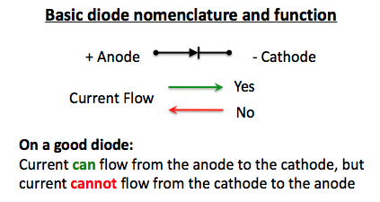
For the test we will do here what we want to do is check each individual diode in the rectifier. How we test each diode is to use the digital multimeter which apply's a small current and then displays the voltage drop thru the diode. The diode is unique in that it will only allow current to flow in one direction which the following figure describes in more detail.
 To perform the test we will simply connect the leads from the digital multimeter to the wires or connecter on the rectifier and check the output. You will do two tests on each diode, one with the leads connected to cause current to flow in one direction and then you will reverse the leads to apply the current in the other direction, so there will be a minimum of eight total tests.
The picture below shows the basic test setup and the three different configurations of rectifiers I will test.

To test the old orange rectifier off of a 1971 CT90 I have I connected the test leads from the digital multimeter as shown below.

I systematically went through and checked each diode by moving the leads from one wire pair to the next and the final results are shown in the table below. In the tables for each of the tests I will describe below when I simplified the description of the red wire with a white stipe to just red to simplify the tables.

So this rectifier checked out as good. One other detail worth pointing out is that just getting a reading when you are supposed to doesn't necessarily mean the reading is good. for a reading to be good it shouldn't be too much different then the other readings, but it doesn't have to be the exact same value.
The next rectifier I checked was the newer configuration off of a 1975 CT90 that incorporates solid state diodes and has a plastic plug on the end of the wires bundle. To check this configuration I attached the leads from the digital multimeter to the blade connections inside the plug as shown below and then systematically went through each wire pair.

The table below has the final results for this rectifier.

This rectifier is bad based on the results of test 2 where I got a reading when I expected to get a reading, but it was significantly different then the other readings. This rectifier also failed test 8 where I did get a reading when I expected not to get a reading.
With the generic solid state rectifier I connected the leads from the digital multimeter as shown in the pictures below.


The generic solid state rectifier has four posts and they are labeled "+", "-", "AC, and "AC". The + post corresponds to the red wire with the white stipe on a typical CT90 rectifier and the - post corresponds to the green wire on a CT90 rectifier and the AC posts correspond to the yellow and pink wires on a CT90 rectifier.
The table below has the final results for the test of this rectifier which tested as good.

As you can see fro the tests above it really is a pretty simple and straight forward task to test a CT90 rectifier.
I also made the video below to help demonstrate the process on how to perform a test of your CT90 Rectifier.
I hope all of the above information is helpful in assisting you in testing your CT90 rectifiers.
Links to Related Posts
CT90 Rectifier Upgrade
Basic Test of a CT90 Condenser
Basic CT90 Ignition Coil Check
Helpful Links (Shop Manuals, Wire Diagram, Model Information, etc.)
Link to page with listing of CT90 parts available on Amazon
Links to Related Posts
CT90 Rectifier Upgrade
Basic Test of a CT90 Condenser
Basic CT90 Ignition Coil Check
If you have an old CT90 that you are trying to bring back to life, I would recommend just going ahead and upgrading your rectifier to a newer more modern solid state design and I made a post here on how to do that yourself. But if you would like to use the rectifier that came with your bike or if you are really trying to restore your CT90 back to the original configuration, I'll show you how to test your rectifier to see if it is good or bad as it's really a very simple test to do.

To do the test you will need a digital multimeter that has a setting to check diodes. The picture below is of my digital multimeter where I have adjusted the setting to do a diode check and if you are using a different brand of multimeter the symbols used to identify the settings for a diode check should be very similar to those shown in the picture of my digital multimeter below.

Before we get into the actual test it is probably good to review what the rectifier in a CT90 actually is.
The rectifier used in a CT90 is more formally known as a Full Bridge Rectifier. The purpose of the rectifier on the CT90 is to take the AC voltage coming through the wires connected to the stator on the CT90's generator and convert the AC voltage into a quasi DC voltage that can charge the battery and provide power to the CT90's electrical system.
The full bridge rectifier used on the CT90 is made up of four diodes arranged as shown in the figure below.

The above figure is representative for either the older plate style rectifier (which is more formally known as a Selenium rectifier and here is a link if you would like more info) or the newer solid state style of rectifiers used on later CT90 and CT110 configurations and also used on upgrades you can do yourself like I describe in another post I did at a link here.
The picture below shows the basic test setup and the three different configurations of rectifiers I will test.

To test the old orange rectifier off of a 1971 CT90 I have I connected the test leads from the digital multimeter as shown below.

I systematically went through and checked each diode by moving the leads from one wire pair to the next and the final results are shown in the table below. In the tables for each of the tests I will describe below when I simplified the description of the red wire with a white stipe to just red to simplify the tables.

So this rectifier checked out as good. One other detail worth pointing out is that just getting a reading when you are supposed to doesn't necessarily mean the reading is good. for a reading to be good it shouldn't be too much different then the other readings, but it doesn't have to be the exact same value.
The next rectifier I checked was the newer configuration off of a 1975 CT90 that incorporates solid state diodes and has a plastic plug on the end of the wires bundle. To check this configuration I attached the leads from the digital multimeter to the blade connections inside the plug as shown below and then systematically went through each wire pair.

The table below has the final results for this rectifier.

This rectifier is bad based on the results of test 2 where I got a reading when I expected to get a reading, but it was significantly different then the other readings. This rectifier also failed test 8 where I did get a reading when I expected not to get a reading.
With the generic solid state rectifier I connected the leads from the digital multimeter as shown in the pictures below.


The generic solid state rectifier has four posts and they are labeled "+", "-", "AC, and "AC". The + post corresponds to the red wire with the white stipe on a typical CT90 rectifier and the - post corresponds to the green wire on a CT90 rectifier and the AC posts correspond to the yellow and pink wires on a CT90 rectifier.
The table below has the final results for the test of this rectifier which tested as good.

As you can see fro the tests above it really is a pretty simple and straight forward task to test a CT90 rectifier.
I also made the video below to help demonstrate the process on how to perform a test of your CT90 Rectifier.
I hope all of the above information is helpful in assisting you in testing your CT90 rectifiers.
Links to Related Posts
CT90 Rectifier Upgrade
Basic Test of a CT90 Condenser
Basic CT90 Ignition Coil Check
Helpful Links (Shop Manuals, Wire Diagram, Model Information, etc.)
Link to page with listing of CT90 parts available on Amazon
Comments
Post a Comment