1970 CT90 Turn Signal and Horn Button Brakedown and Assembly
I was going through and cleaning up the left lever lever assembly that retains the turn signal switch and horn button and thought I would share a few shots of the detail parts and how it is assembled. If you are missing or have a rusted detent ball I have found that a 5/32 ball bearing that you can get at a bicycle shop of good hardware store is a good substitute.
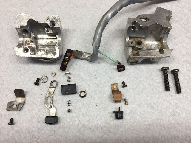
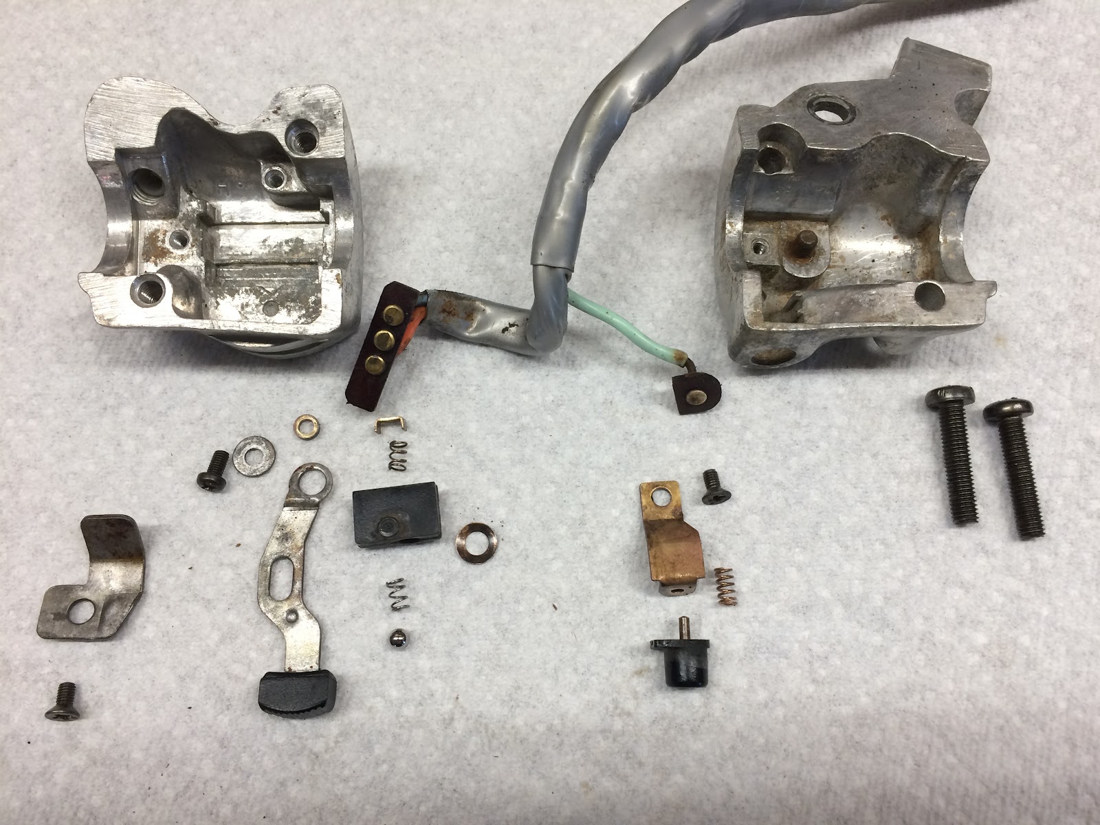
Here is an overall shot of all the components:
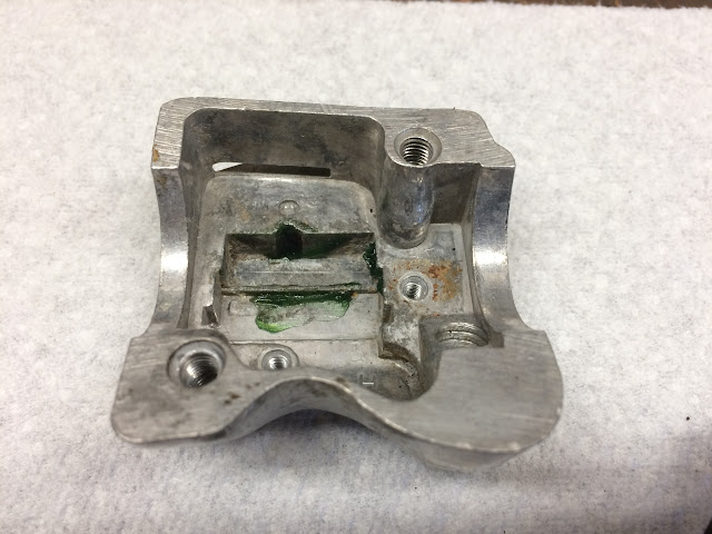
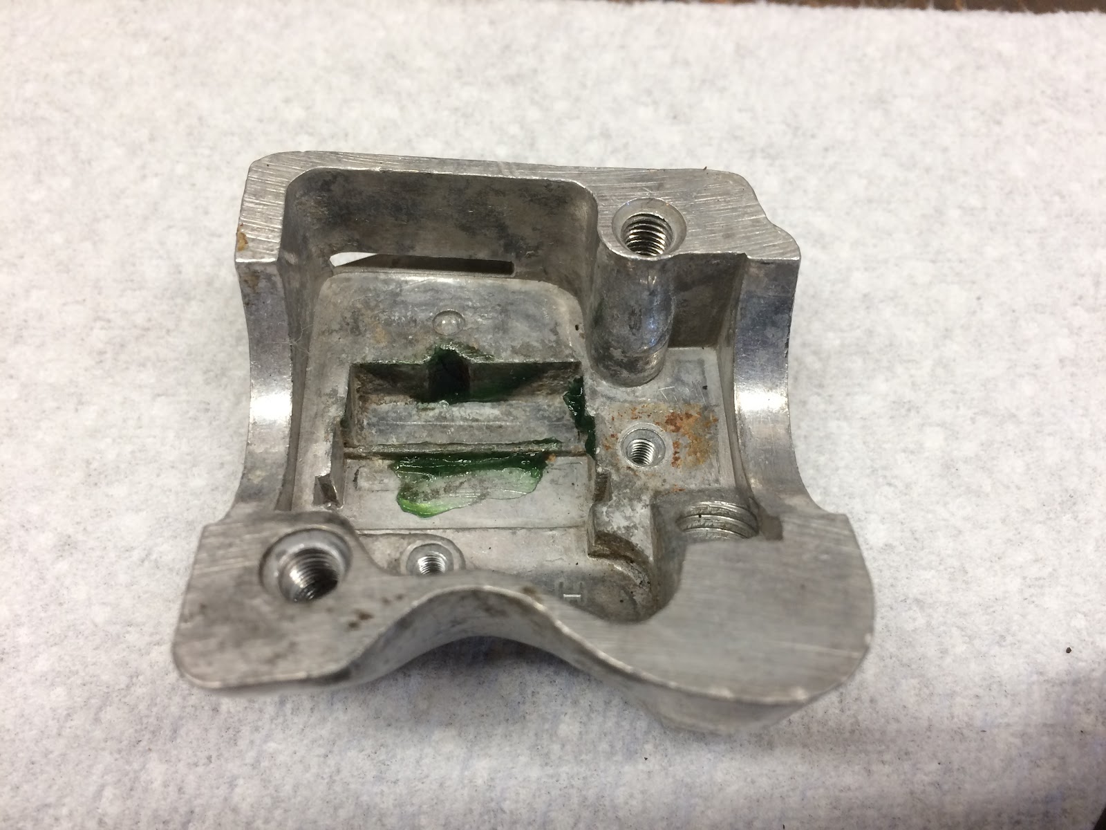
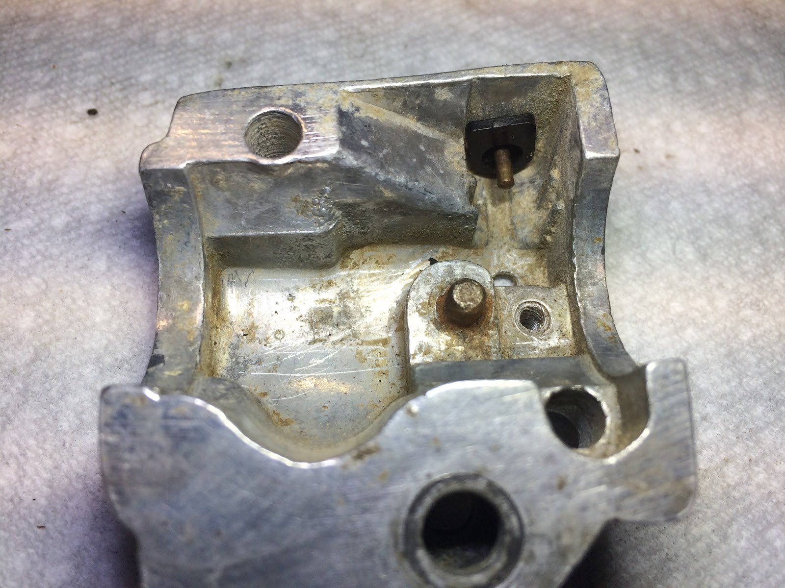
I first step in assembling the turn signal switch is to apply a little grease to the detent and guide feature on the housing that retains the switch assembly.
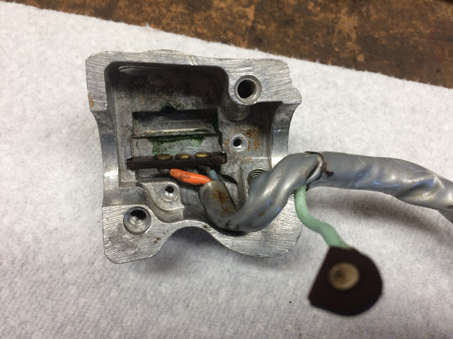
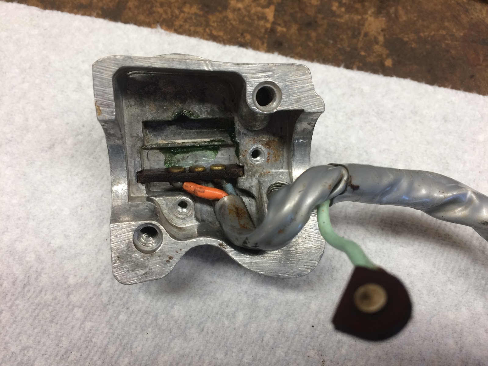
The next step is to insert the contact feature of the wire harness into the slots in the housing.
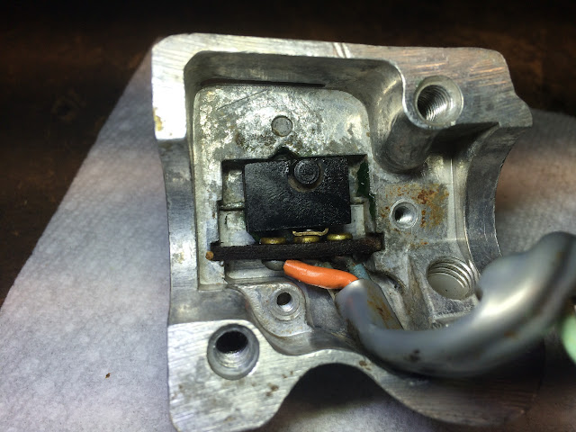
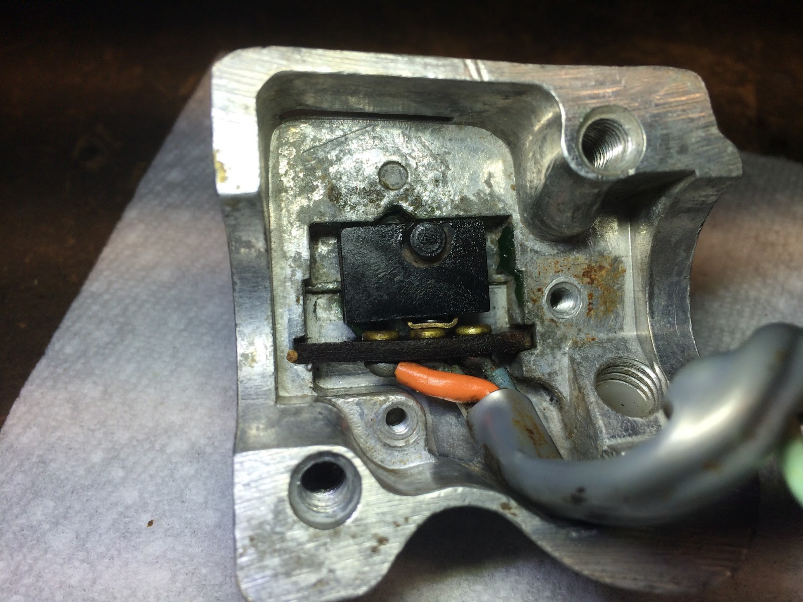
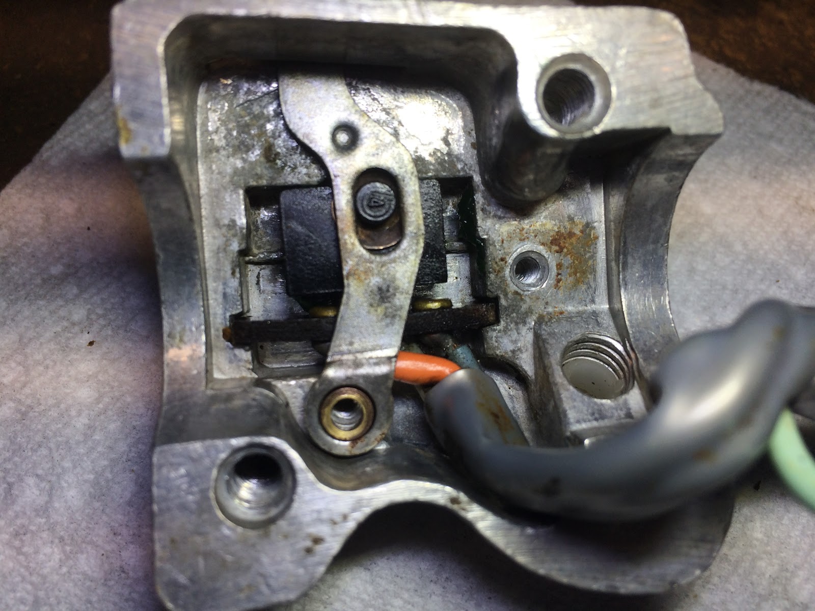
The next part is the tricky part and requires some patience. Into the black slider component you need to assembly the spring and the sliding U shaped contact that will mate with the contact feature of the wire harness and also then assemble the spring and detent ball into the other side of the black slider component and then while keeping the ball detent and sliding contact compressed, assemble the black slider assemble into the housing. If you and using a tool to help you with this process you need to be careful and not pry on the contact feature of the wire harness as the pheonilic board holding the contacts can break.
At this point I'll spray a little dielectric grease on the contacts to help keep them clean and enable smoother operation of the switch.
You next insert the turn signal lever making sure to include the small bushing where the lever will pivot in use and also the cupped washer that goes between the black slider and the lever and the cupped side should be facing up.

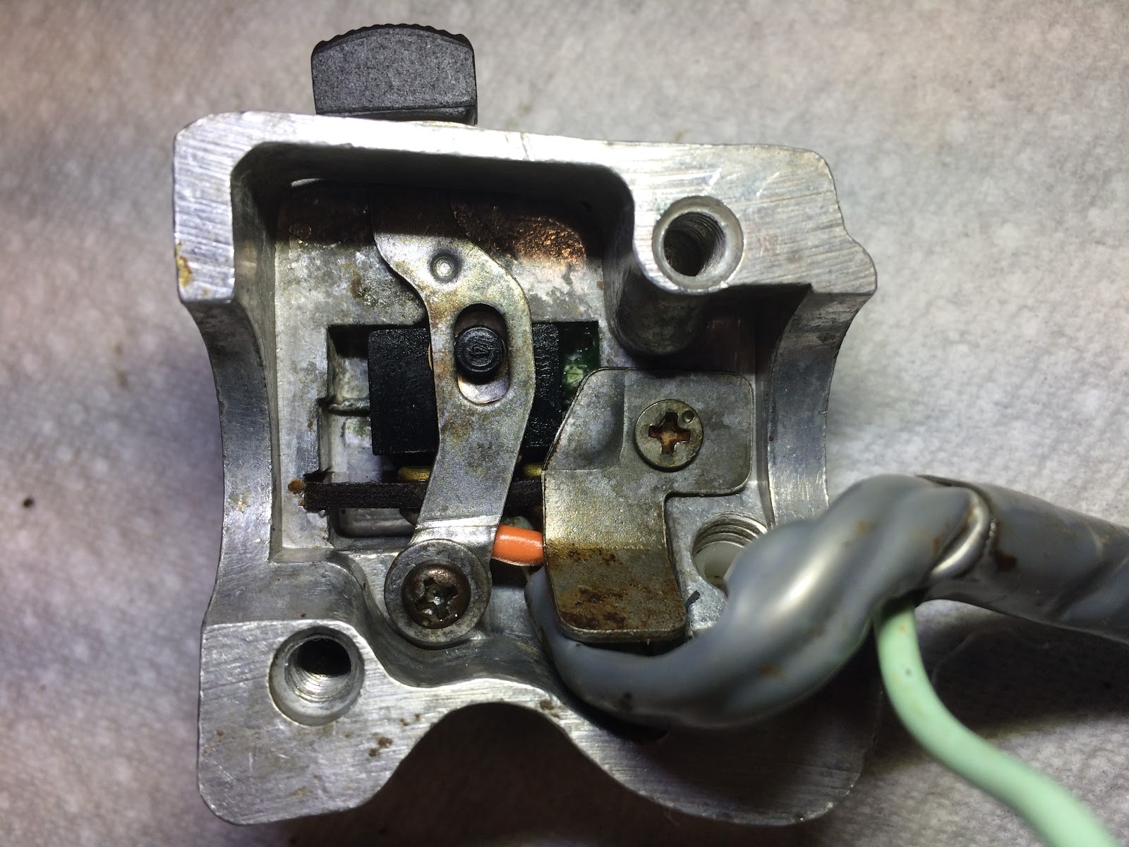
Next install the screw and washer to retain the lever and then instal the harness retainer and screw.

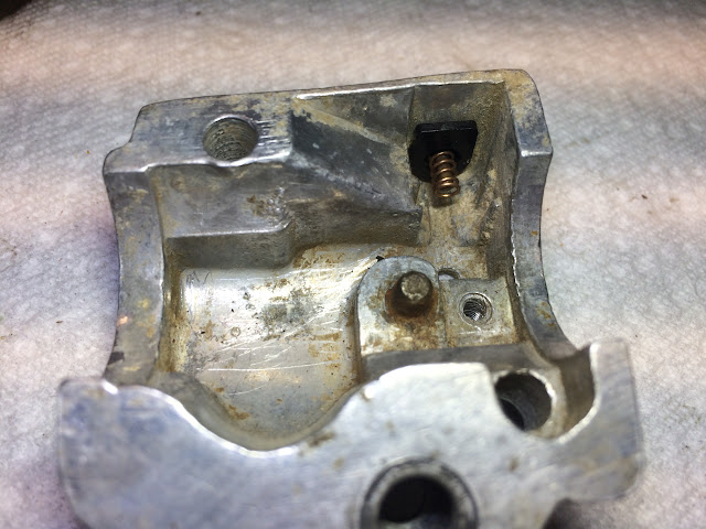
With that side of the lever assembly complete we need to now complete the horn side of the assembly. The first step is to insert the horn button into the housing.

Next slip the copper spring of the contact post on the horn button.
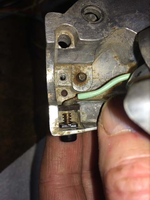
Next slide the horn contact from the wire harness into the mating slot on the housing.
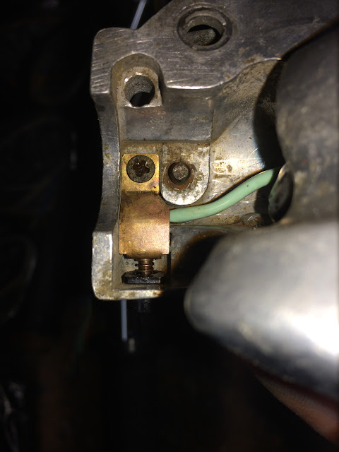
The last step is to install the horn button guide and wire harness retainer buy slipping it between the end of the horn button and contact until the hole in the horn button guide is aligned with the post on the horn button and then move it in the direction of the horn button until the screw that retains the guide can be installed. The lever assembly is now complete and ready to install back on the handle bar.
Here is an overall shot of all the components:
I first step in assembling the turn signal switch is to apply a little grease to the detent and guide feature on the housing that retains the switch assembly.
The next step is to insert the contact feature of the wire harness into the slots in the housing.
The next part is the tricky part and requires some patience. Into the black slider component you need to assembly the spring and the sliding U shaped contact that will mate with the contact feature of the wire harness and also then assemble the spring and detent ball into the other side of the black slider component and then while keeping the ball detent and sliding contact compressed, assemble the black slider assemble into the housing. If you and using a tool to help you with this process you need to be careful and not pry on the contact feature of the wire harness as the pheonilic board holding the contacts can break.
At this point I'll spray a little dielectric grease on the contacts to help keep them clean and enable smoother operation of the switch.

You next insert the turn signal lever making sure to include the small bushing where the lever will pivot in use and also the cupped washer that goes between the black slider and the lever and the cupped side should be facing up.
Next install the screw and washer to retain the lever and then instal the harness retainer and screw.
With that side of the lever assembly complete we need to now complete the horn side of the assembly. The first step is to insert the horn button into the housing.
Next slip the copper spring of the contact post on the horn button.

Next slide the horn contact from the wire harness into the mating slot on the housing.

The last step is to install the horn button guide and wire harness retainer buy slipping it between the end of the horn button and contact until the hole in the horn button guide is aligned with the post on the horn button and then move it in the direction of the horn button until the screw that retains the guide can be installed. The lever assembly is now complete and ready to install back on the handle bar.

Helpful Links (Shop Manuals, Wire Diagram, Model Information, etc.)
Thanks! Today's project is a new button, spring, and horn on my 1974 CT90!
ReplyDeleteGreat info thanks much.
ReplyDeleteTurn signal housing is still wired up to bars, so will be more difficult. Are there any specific tweezers that can be used to compress the spring and the sliding U shaped contact that will mate with the contact feature of the wire harness and also then assemble the spring and detent ball into the other side of the black slider component and then while keeping the ball detent and sliding contact compressed
ReplyDelete