Honda CT200 Step by Step Engine Reassembly Guide
I recently picked up a CT200 that wasn't running, but seemed to be in decent shape where the engine would turn over and had signs of good compression. I had rebuilt one CT200 a couple of years ago and sold the bike and since that time I started this blog and because I have had such a good response with the post I did on reassembling a CT90 engine, I decided to take the time to go through the engine of my new CT200 and document the reassembly in this post. Another reason I am going through this engine is that this may end up being a bike I will keep for a while and it seems like all old CT's that I pick up have slime in the engine and the clutch will end up slipping sooner or later, so now is as good a time as any to tear it apart, clean, and then reassemble the engine to avoid any problems in the future. I plan on taking the same approach I did with the CT90 engine reassembly post where I document in detail the step by step process on how everything goes back together in case others were interested in knowing what the inner workings of a CT200 push rod engine look like.
Links to Related Posts:
My Honda CT90 and CT200 Clutch and Headset Nut Tool
Cut away of CT90 Engine - CT90 Engine Exposed!
Honda CT200 Engine Fasteners
Repairing Damaged CT90 Spark Plug Threads Using a Time-Sert Thread Insert
CT90 Clutch Pack Assembly Detail Build-up
Painting Honda CT90 Side Cases
Making a Low Cost Clutch Holding Tool for Your CT90
Building a Basic Timing Light fro a Harbor Freight LED Light
A Simple Valve Spring Compressor
A Simple Way to Check Your Valve Seats
Product Review - Shindy Valve Set 07-002
If you've thought about tearing your own CT200's engine apart, but have avoided it because you thought it might be two difficult, you should really give it a try. The CT200 engine is really a very easy engine to work on and is difficult to screw up when you reassemble it as everything goes together so easily.
Also, if your interested in how the inner components of a CT200 engine actually work, please take a look at a video I made here at this link which shows in detail the inner workings of an operating CT90 engine using a cut-away engine I machined up. While the CT90 uses an overhead cam compared to the push-rod CT200, the clutch and transmission are very similar between the two engines. When I get enough spare CT200 engine parts I plan on making a similar video.
As I outline how I go about reassembling the engine, I may not use the official terminology for what each one of the parts may be called by Honda, but you should be able to get an idea of which physical part I am talking about. There are a number of fasteners that should be properly torqued during the assembly process and while I don't call out those torque values here you can easily look them up at the links I have to Honda manuals on my Helpful Links page.
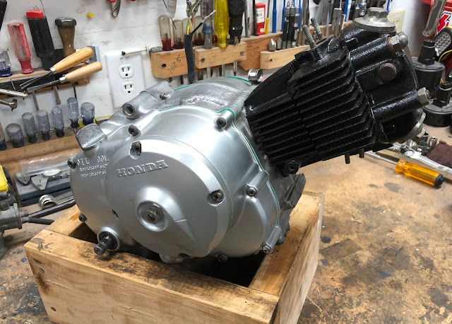
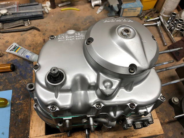
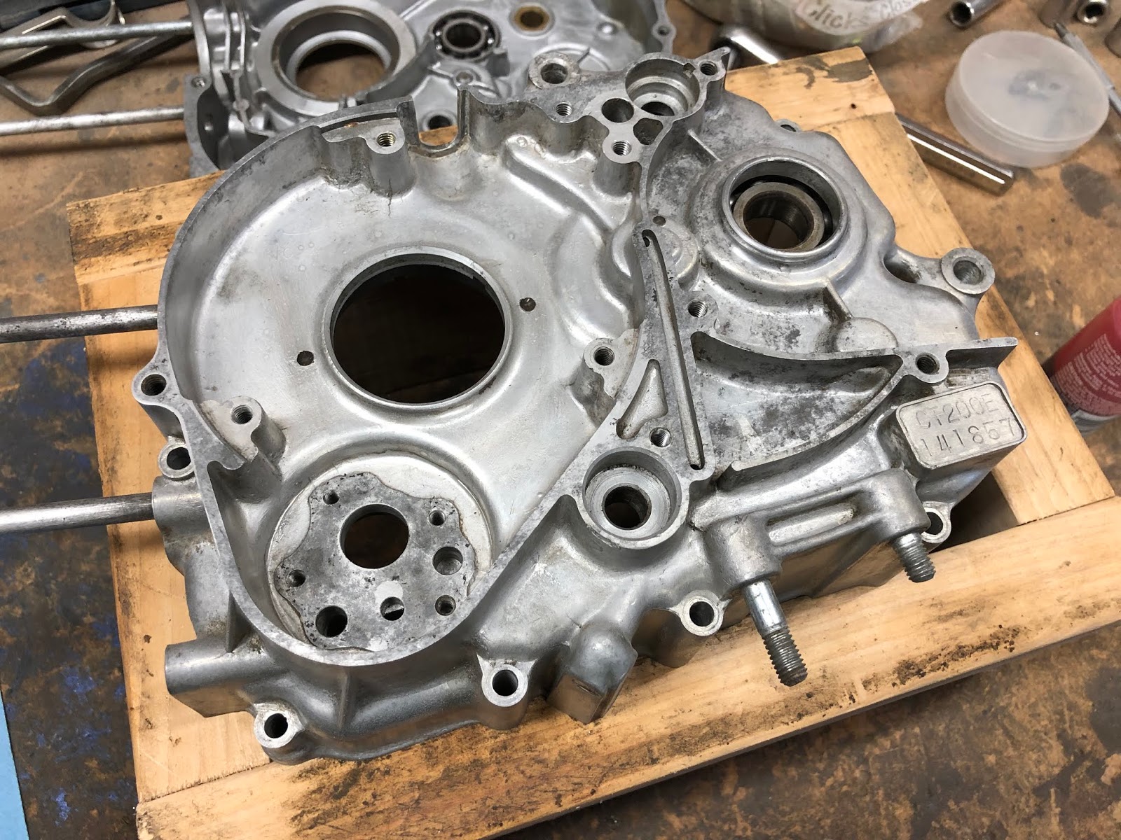
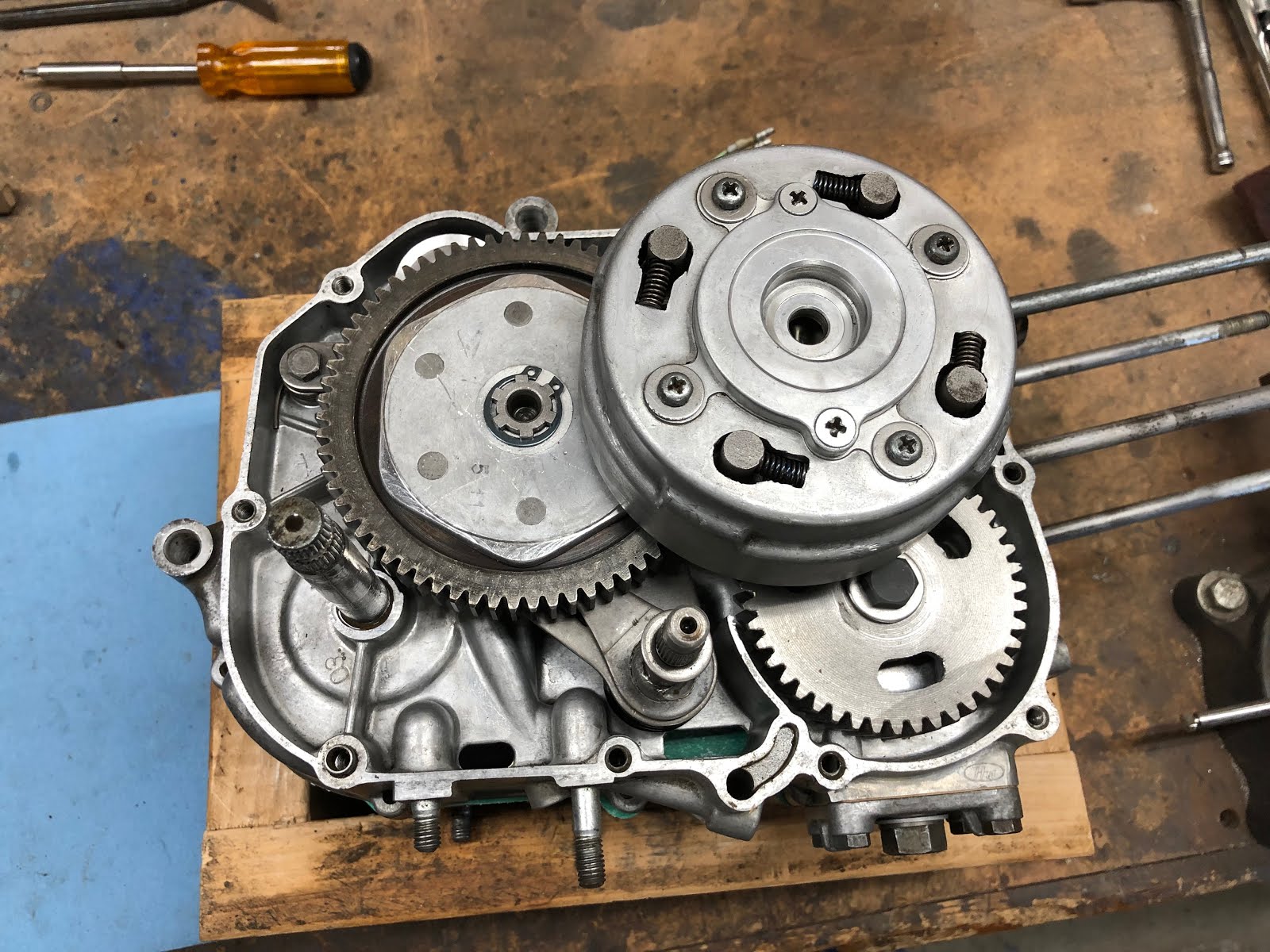
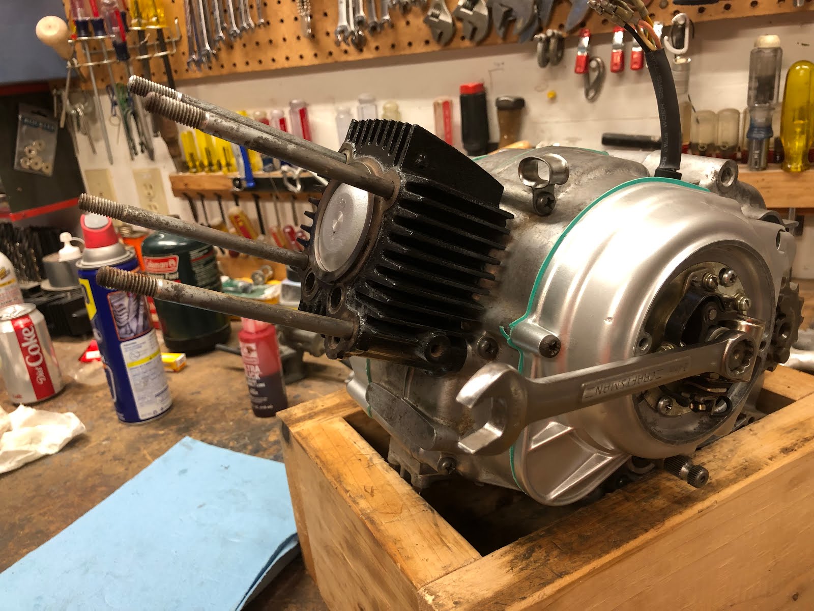
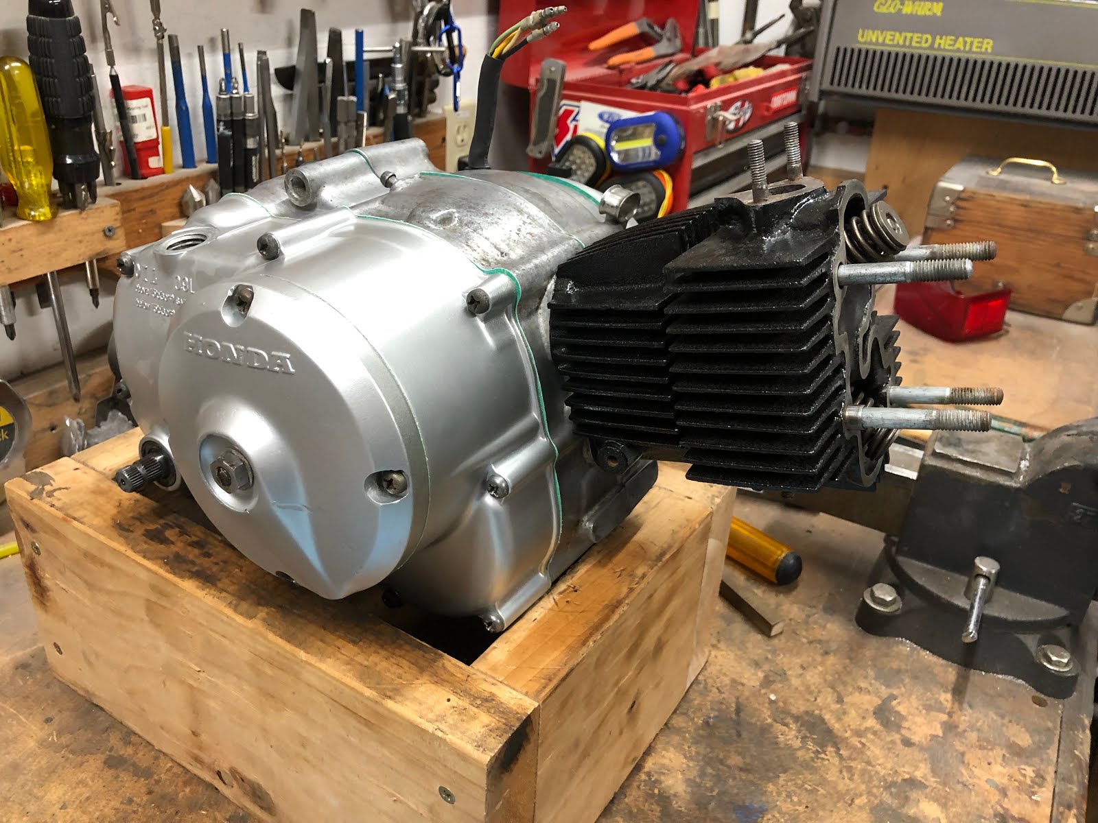
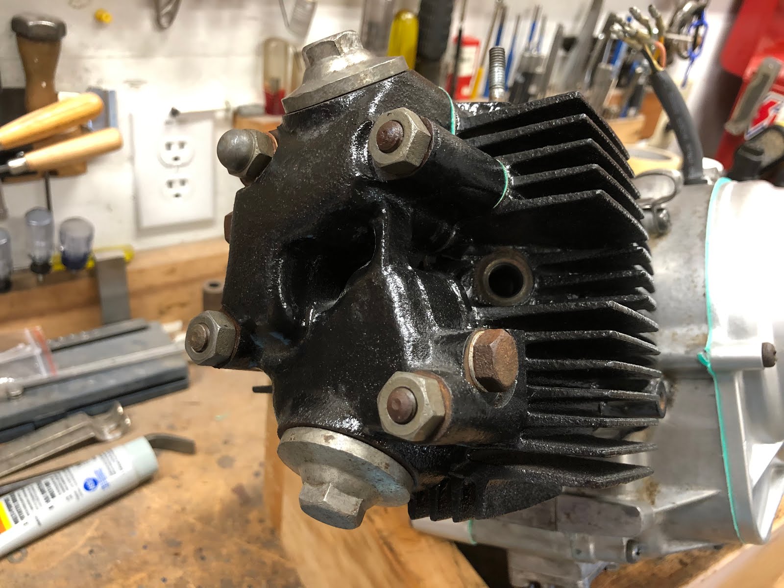
Here is a shot of the engine at the end of the rebuilding effort.
Before I started reassembling the engine, I took everything apart and cleaned and inspected all the parts, replaced any screws or fasteners that got buggered up during the disassembly process. I didn't do it with this engine, but I think its always a go idea to switch out all of the fasteners that hold the cases together to socket head screws which I think is well worth the cost as it makes it very easy to disassemble the engine in the future.
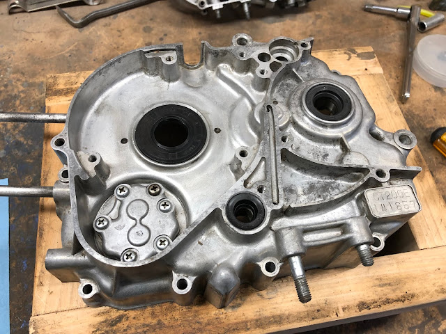
Here is a picture of the majority of the parts that go into a CT200 engine. The side cases shown were painted following a process I shared in another post I made here at this link on how to paint your ct90 side cases.

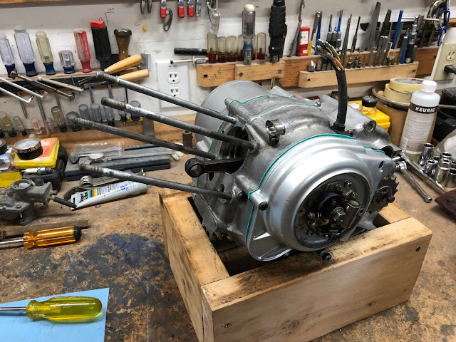
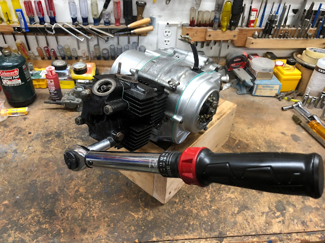
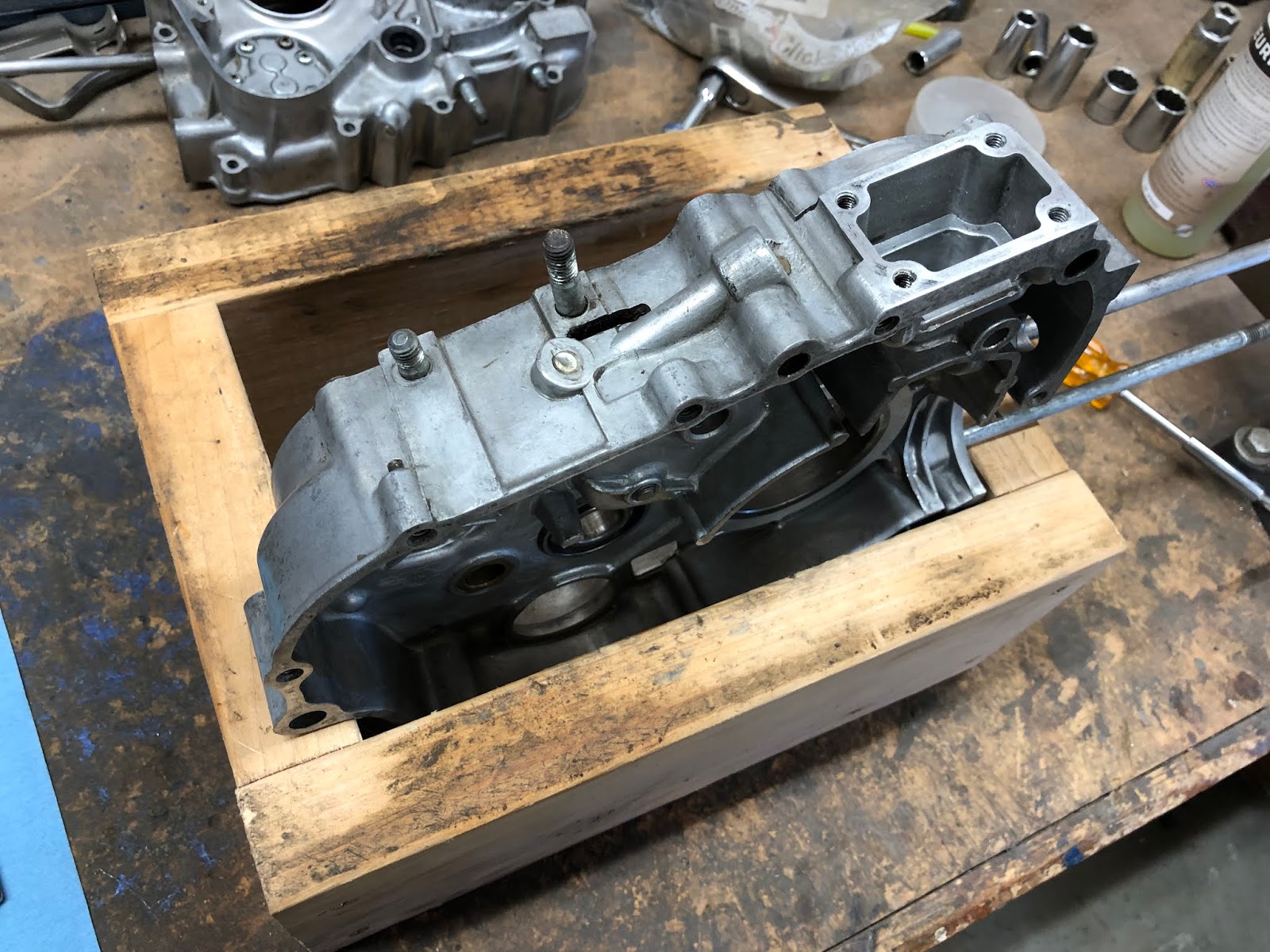
One item that helps make the assembly process that much easier is a simple engine stand made from four pieces of wood like the one I use in the picture below.

The dimensions for the stand that I use are that it is 13 inches long, 10 1/8 inches wide, and 5 1/2 inches high. I made mine from a scrap 2 x 6 I had in my shop. Having some sort of stand like this does make the assembly process that much easier.
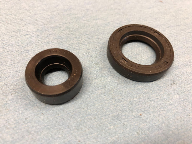
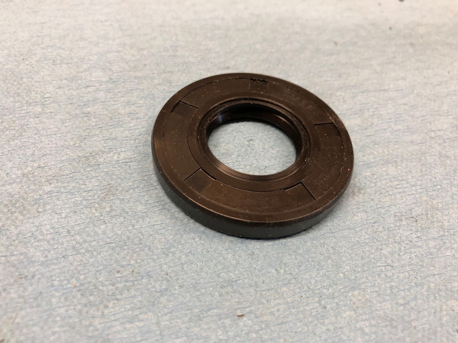
Before you get started you will also need to have a set of gaskets and shaft seals. For this CT200 engine I purchased a Bee gasket set on eBay which seems to have the best price, but it is also available here at this link on Amazon. For the shaft seals I ordered off of eBay that seem to work just fine.

The one thing I did find with the Bee gasket set that it wasn't really complete as it was missing the oil pump gaskets, the gasket that seals the oil screen cover, and the thin o-ring that goes on the cover for the clutch assembly. I was able to order the gaskets for the oil pump and oil screen off of eBay, but I couldn't find the o-ring for the clutch cover, but I was lucky that the one I have is in good enough shape to reuse.

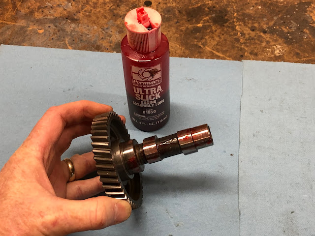
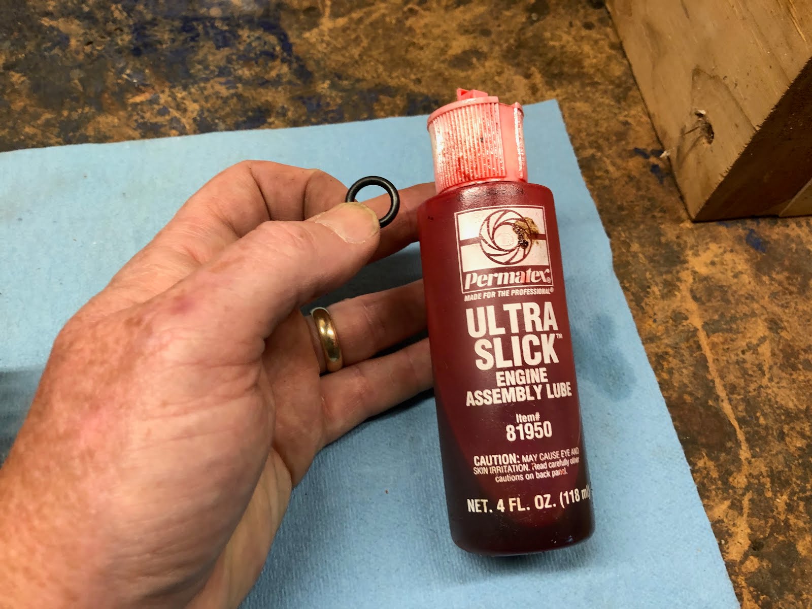
Another detail worth pointing out is that it is always a good idea to apply a little oil or assembly lube to any metal surface that will run against another to help provide some lubrication during the initial start-up of the engine prior to the oil getting circulated. I use Permatex Ultra Slick also available on Amazon.

The first thing I did in starting to put this CT200 engine back together was to do some sub assembly work on the center and side cases. I'll start with installing the parts that make up the oil pump assembly into the left side case that will ultimately hold the generator assembly.

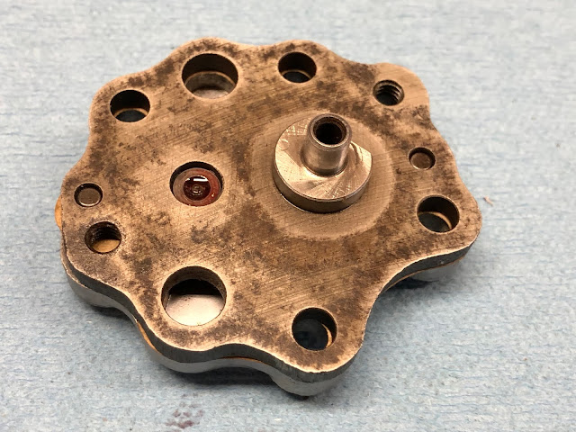
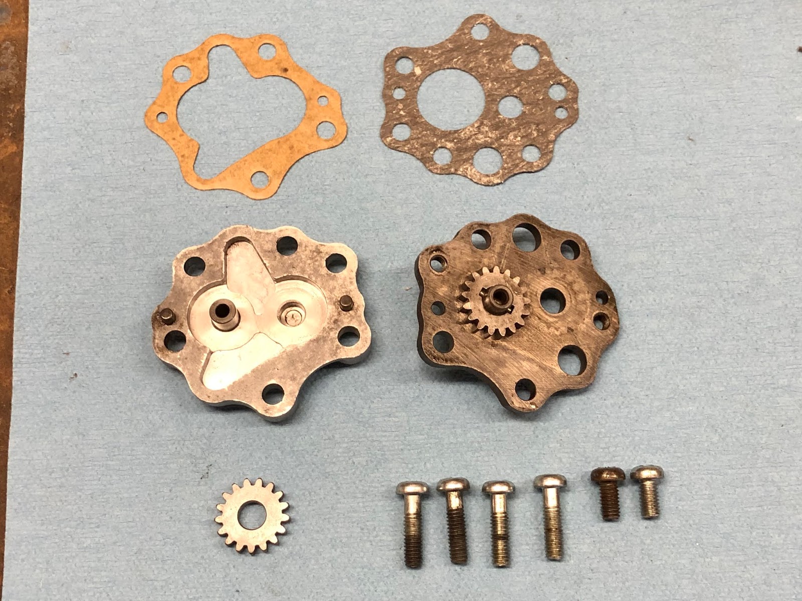
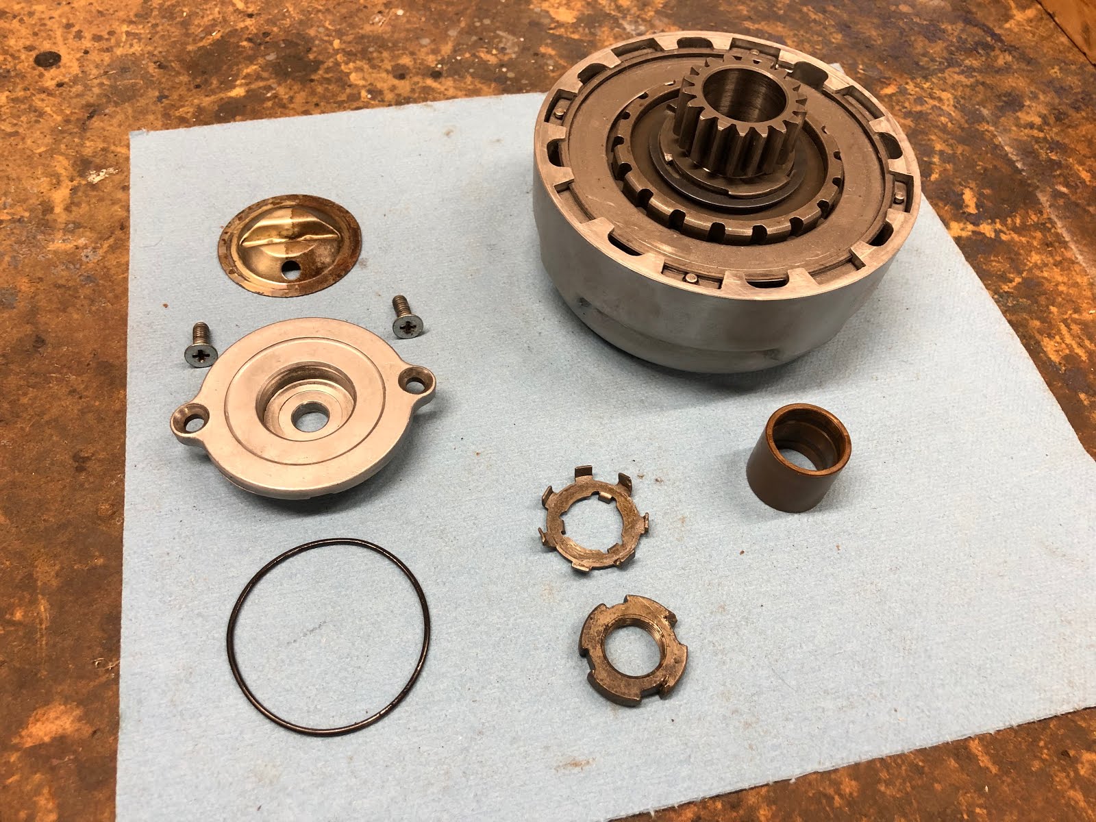
Here are the parts that make up the oil pump assembly:

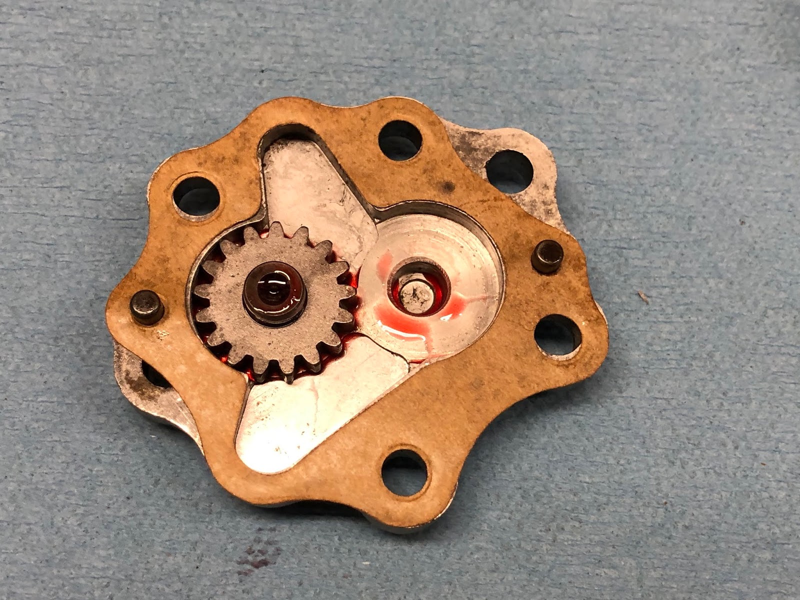
I'll start by assembling the oil pump first and then install it into the housing. The first step is to install the loose gear of the pump with a little lube on the post on the aluminum half of the pump housing.


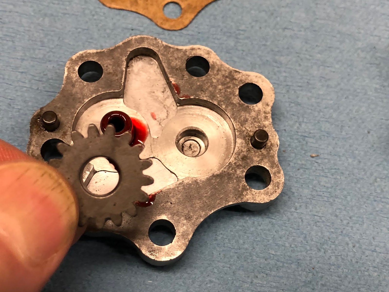
Next I'll install the gasket that goes between the two major components that make up the oil pump.

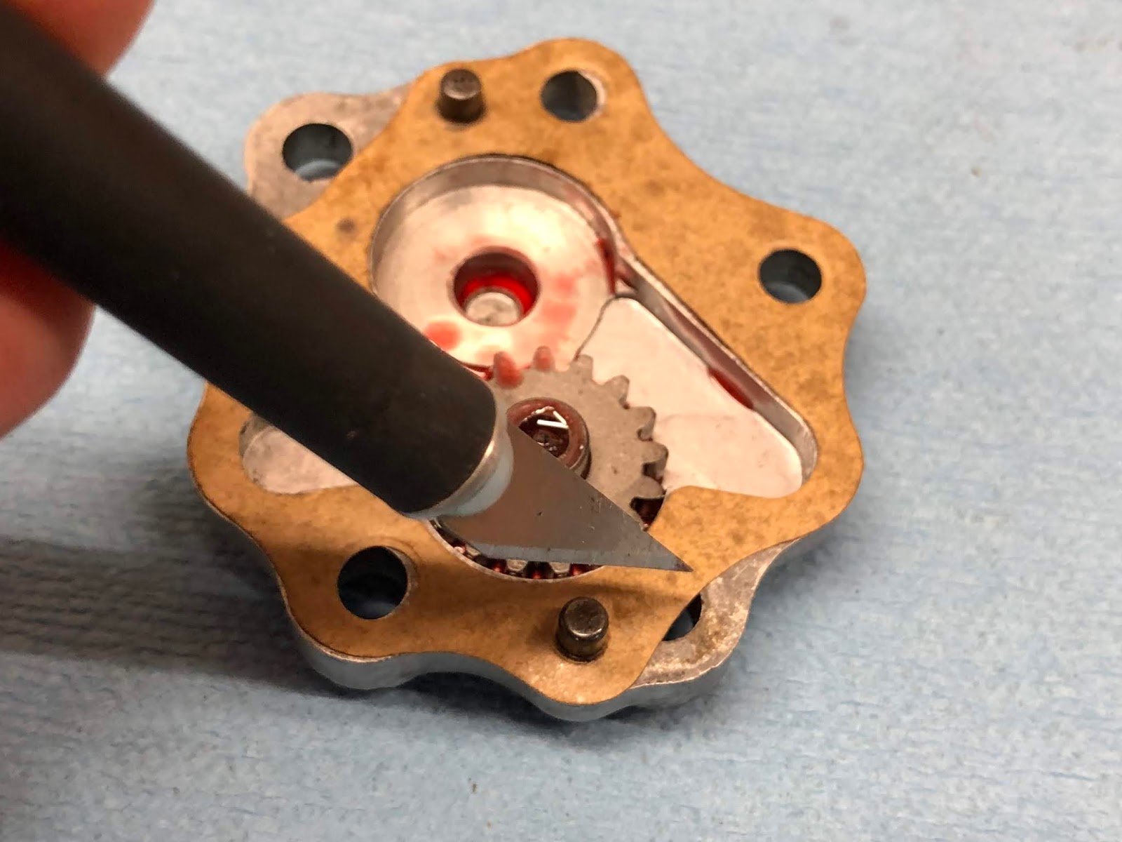
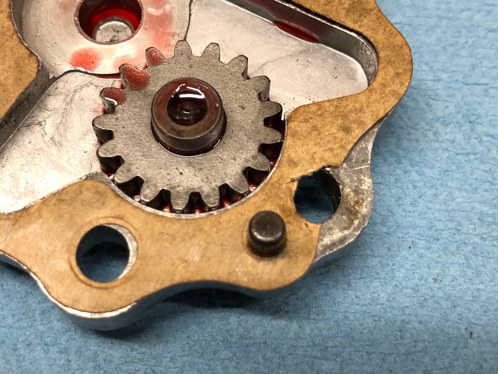
I noticed that the gasket partially covered one of the holes in the housing so I took an excato knife and tried the gasket as needed to unblock the hole.


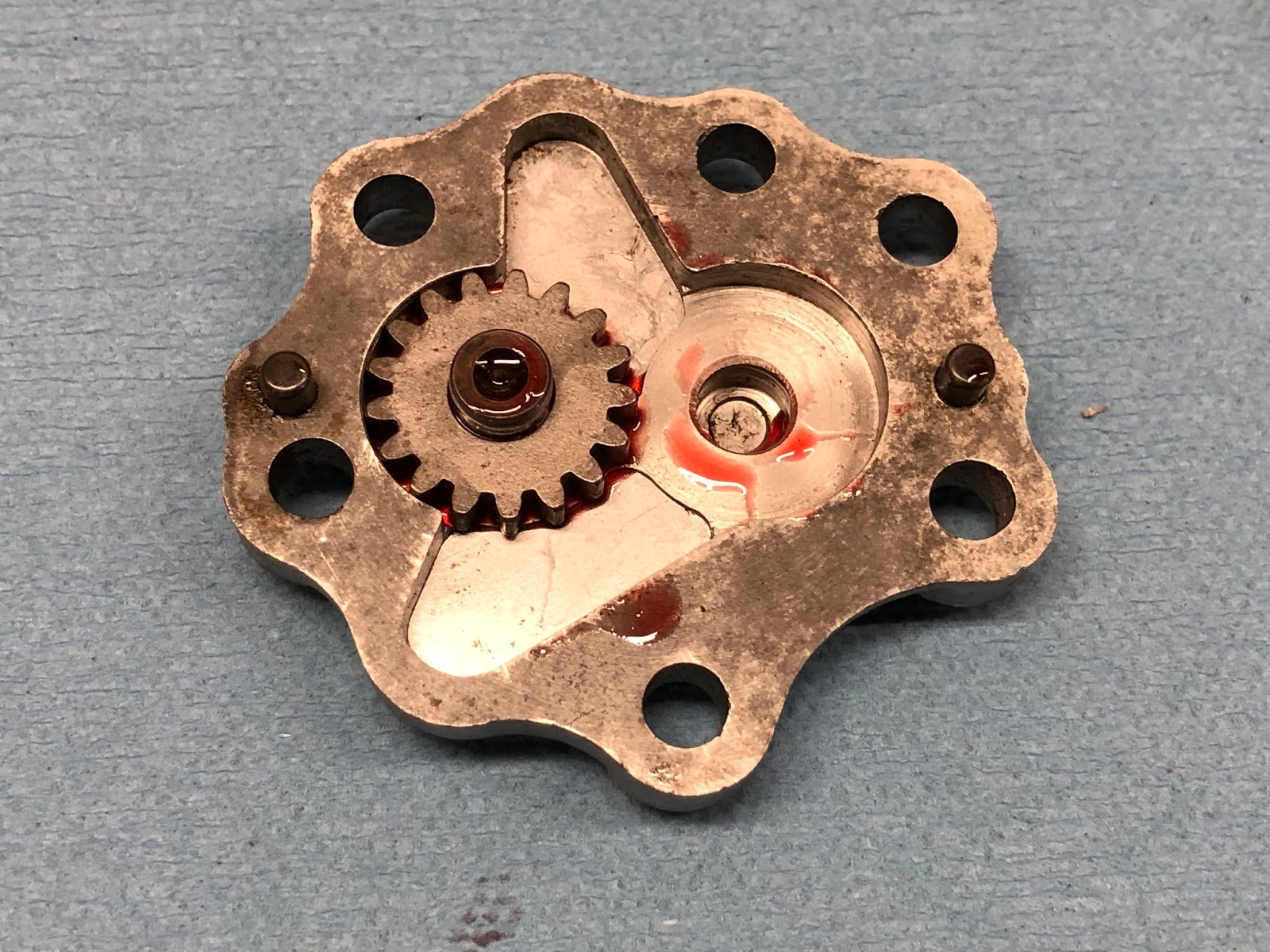
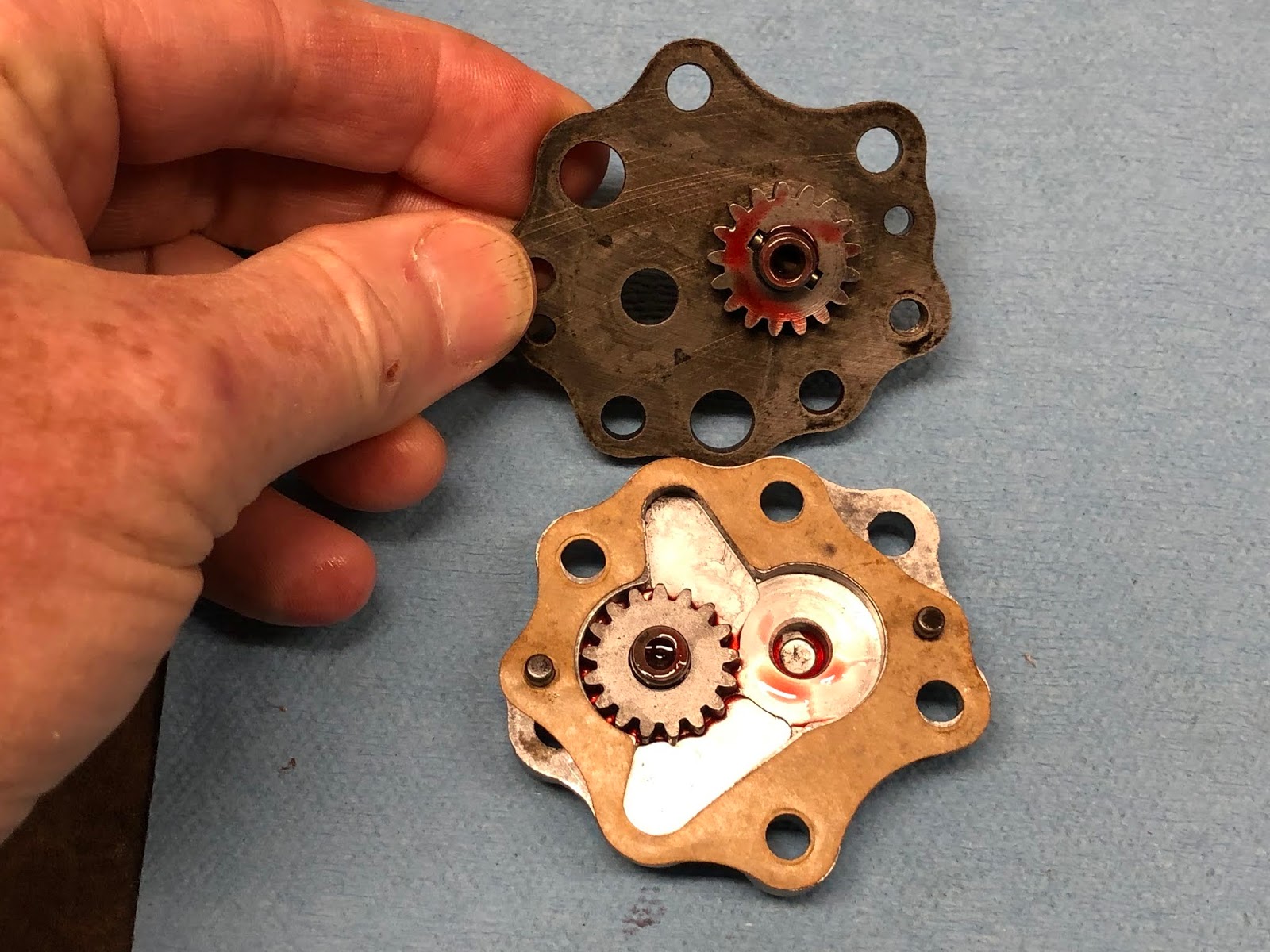
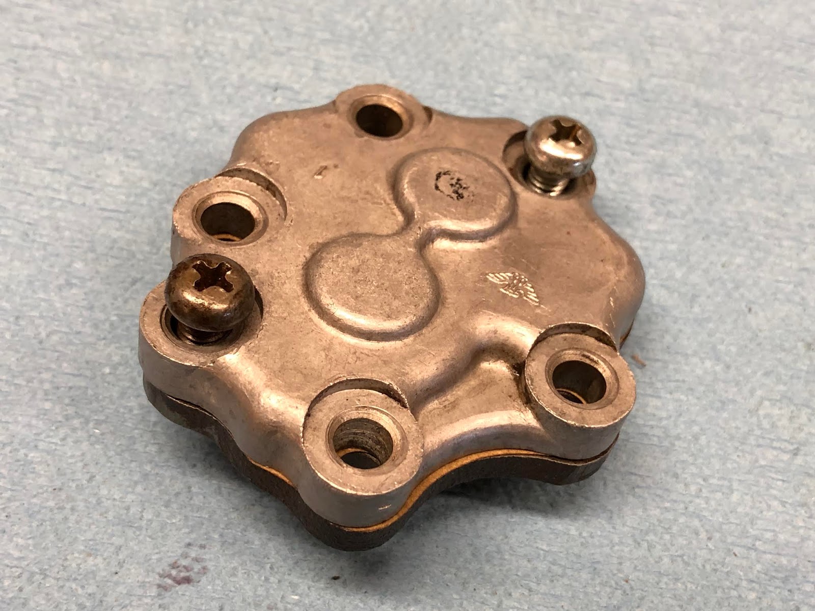
I then installed the steel housing half of the oil pump that has the other gear already installed on to the aluminum half of the pump. I then turned over the assembly and installed the two shorter screws that hold these two housings together and then the pump was ready to install.


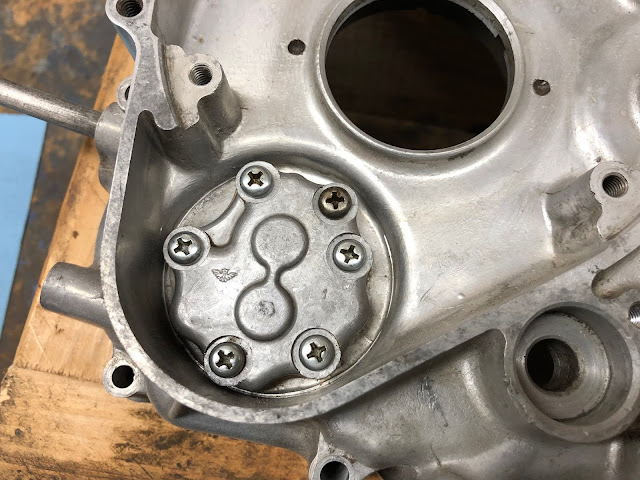
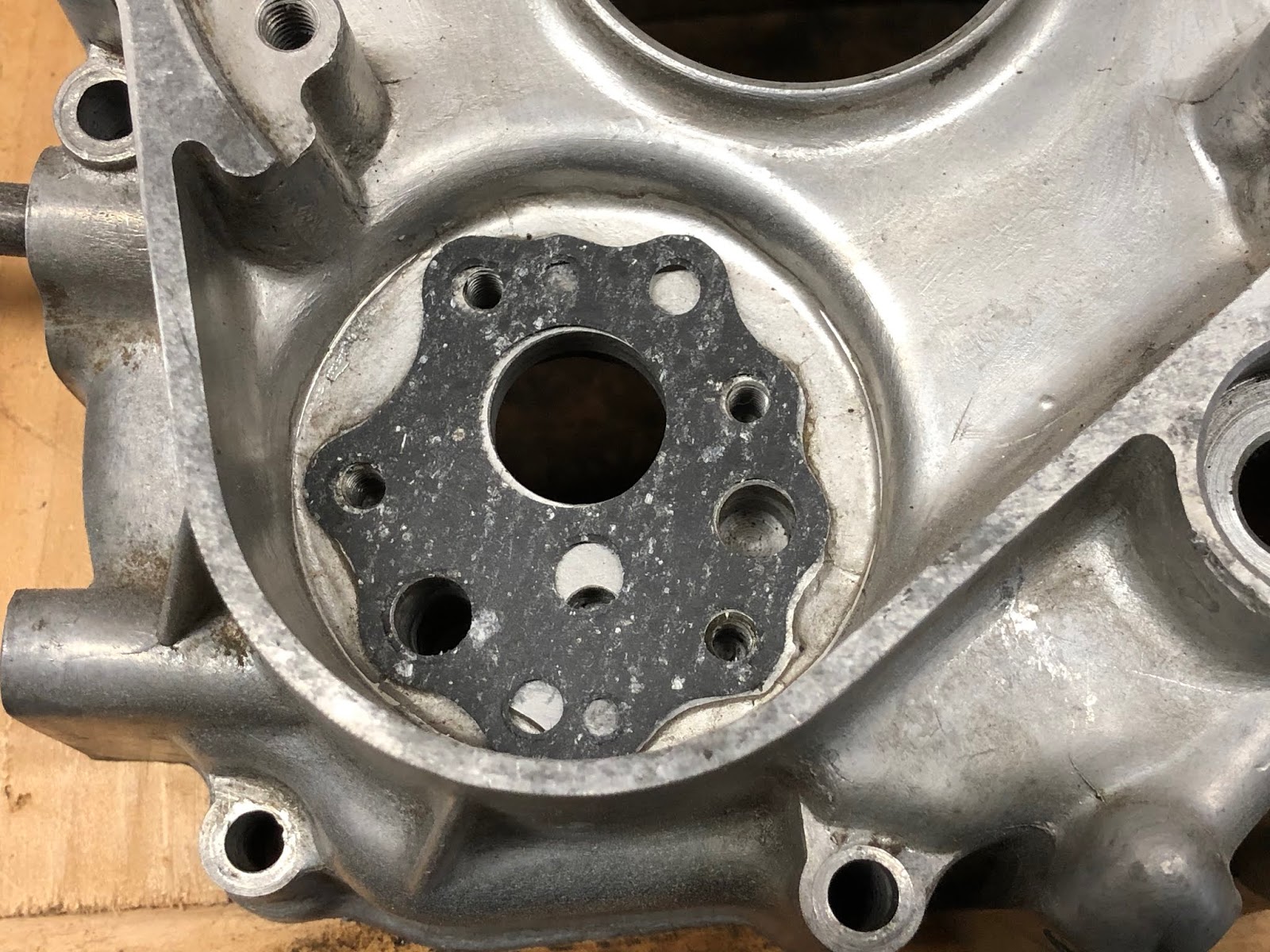
I next placed the base gasket for the oil pump in the left center housing and installed the pump using the four longer screws.

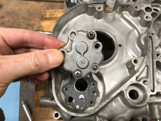
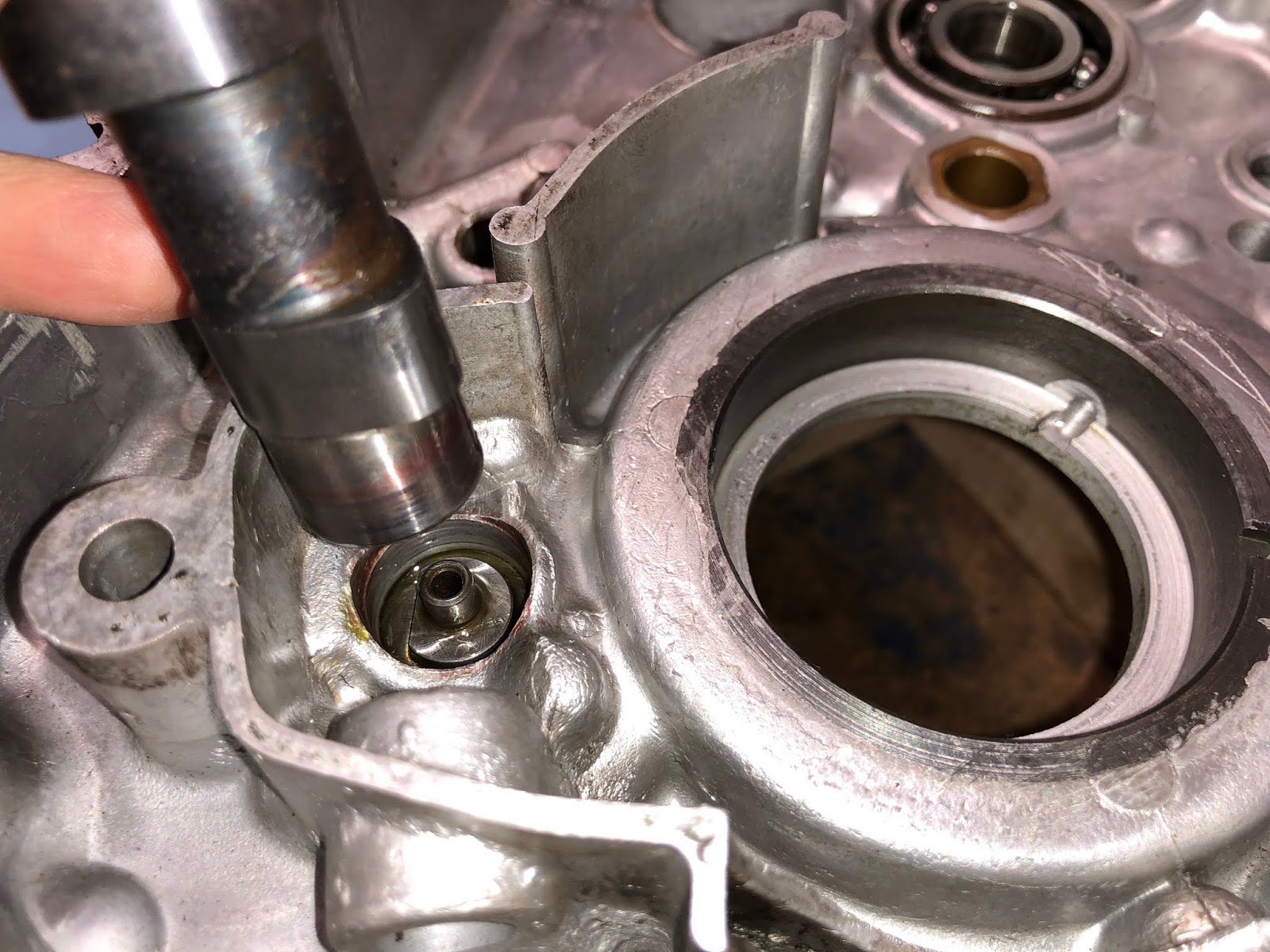
To make sure that there is nothing wrong with the installed oil pump assembly, I'll take the cam shaft and insert it from the inside of the housing so it is engaged with the feature that drives the oil pump and rotate the oil pump to verify that the internal gears of the pump rotate freely.

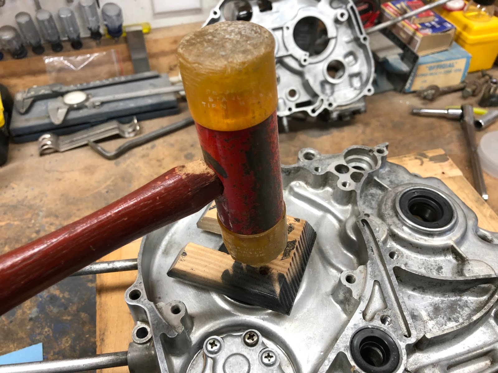
Next I will install the three seals that go into the left center housing starting with the seals for the output shaft that will hold the drive sprocket and the gear shift shaft.
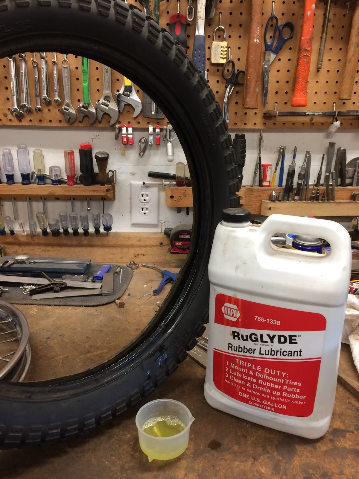
When installing seals like these I will generally apply a very light coat of RuGlyde to the outside diameter of the seal our interior pocket of the bore to help with the installation. RuGlyde is a rubber lubricant for mounting tires, but has a number of other uses and is handy to have around the shop.

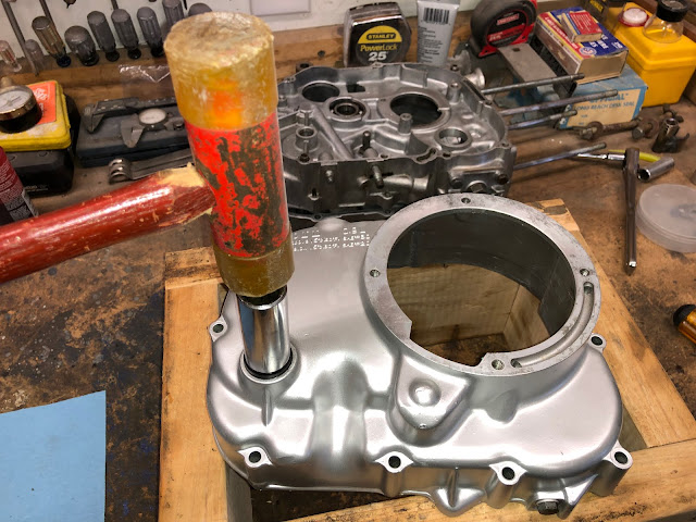
I will use something like the back of a socket that is close to the diameter of the seal as a seal driver and lightly drive each seal into place.


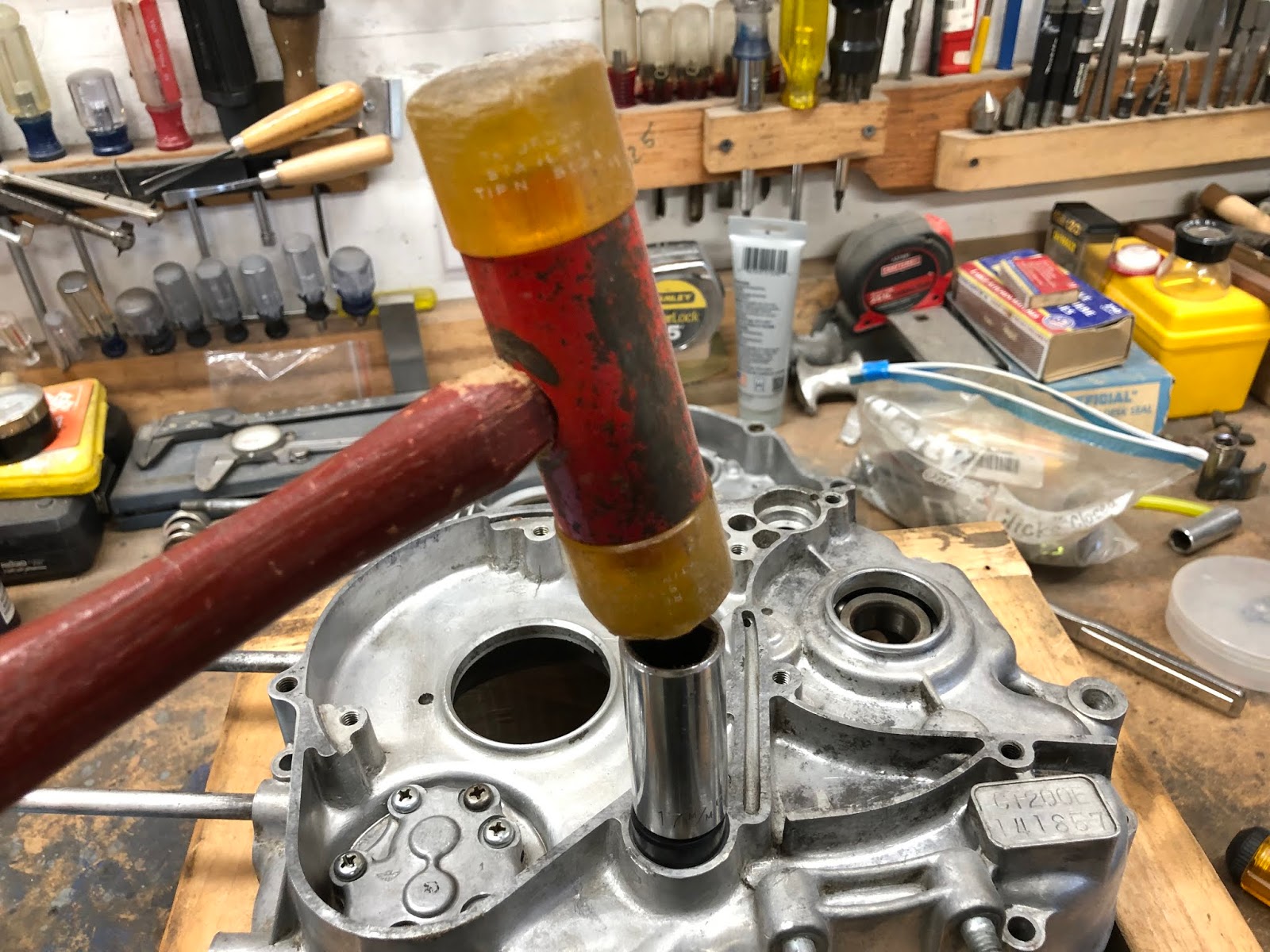
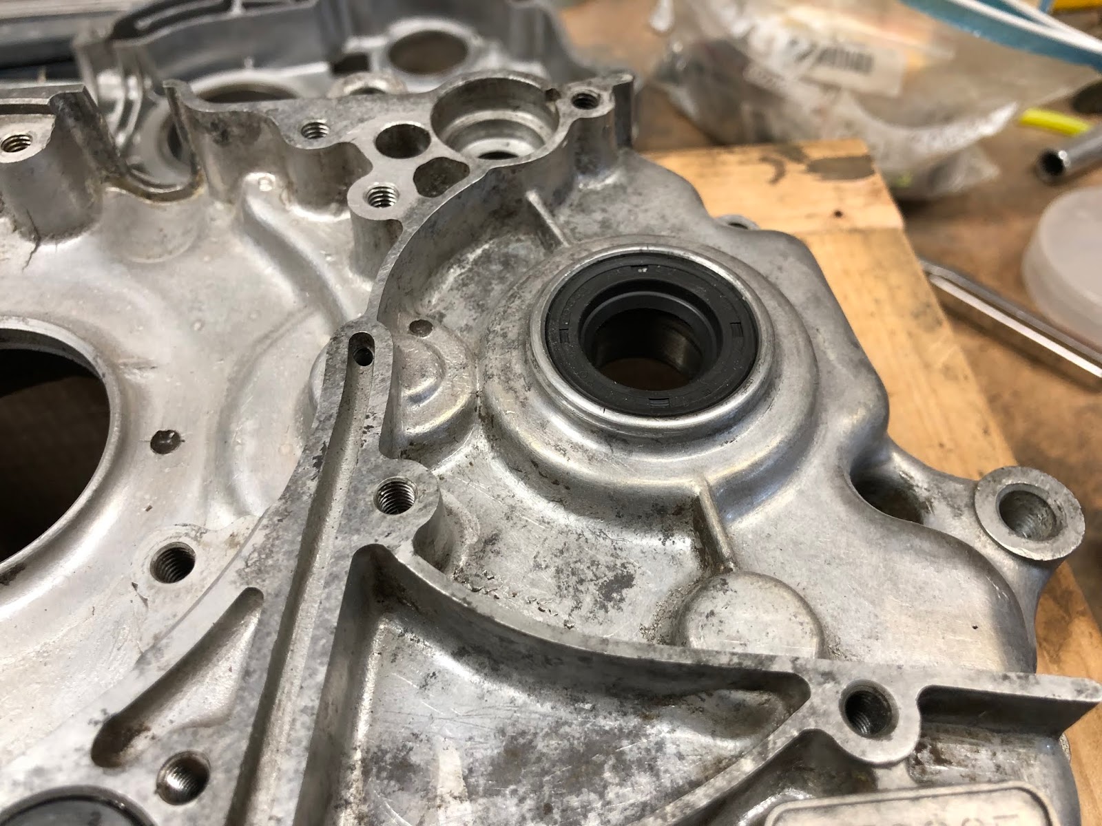
Following the same process I will install the seal into the opening for the crank that keeps oil from the generator cavity. In this situation I used a scrap block of wood as a seal driver and installed the seal so that it was flush to the rim of the hole it was being installed into.


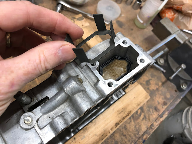
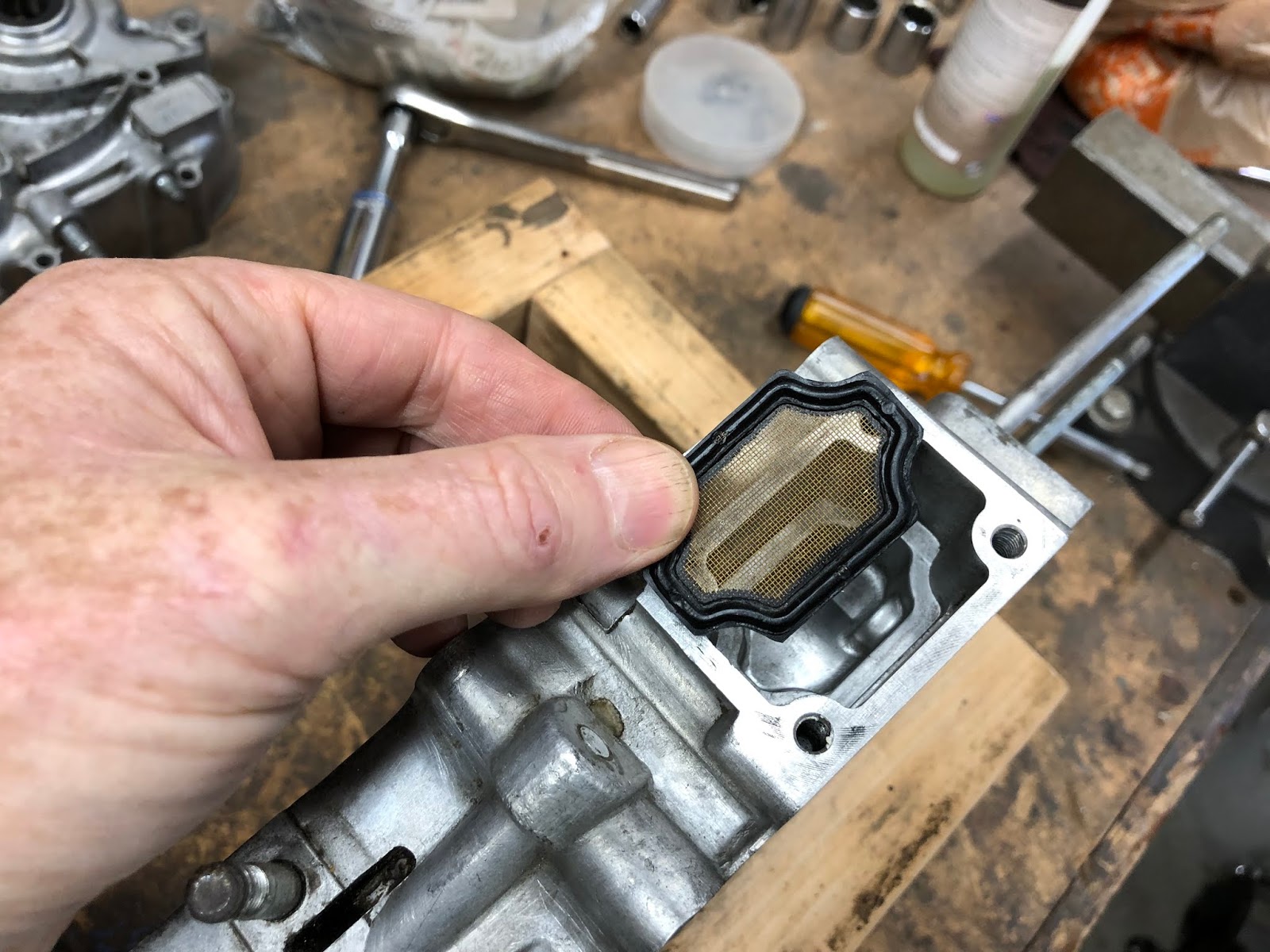
Next I will move to the right center housing and install the oil screen components, cover and drain plug on to the bottom of the housing.

I'll place the housing with the oil filter cavity facing up to make the installation easier.

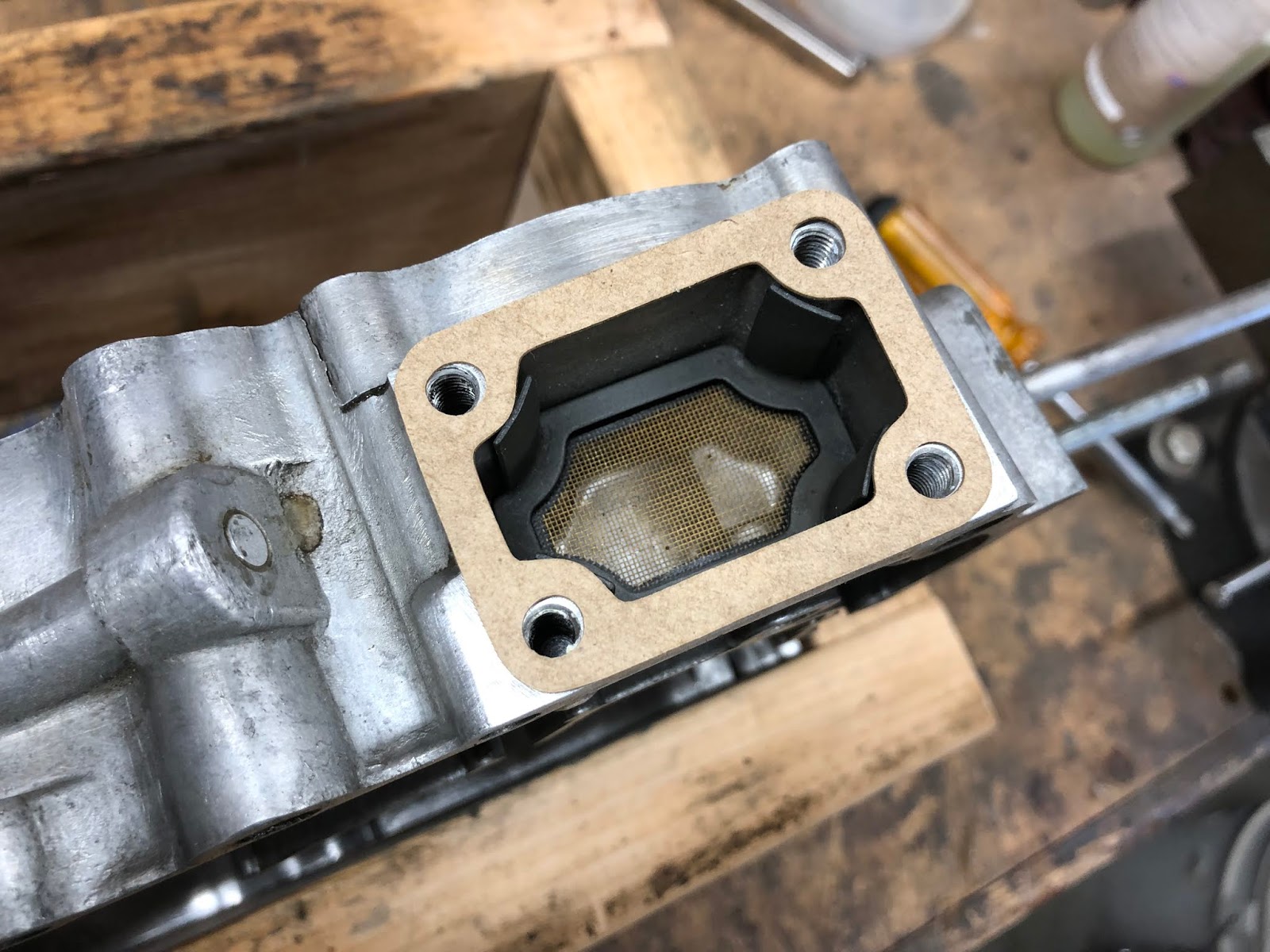
I'll next drop in the oil screen followed by the oil screen support and then place the gasket for the cover and install the four fasteners that hold on the cover.


Lastly I'll install the drain plug and the aluminum crush washer that its as a seal for the drain plug.
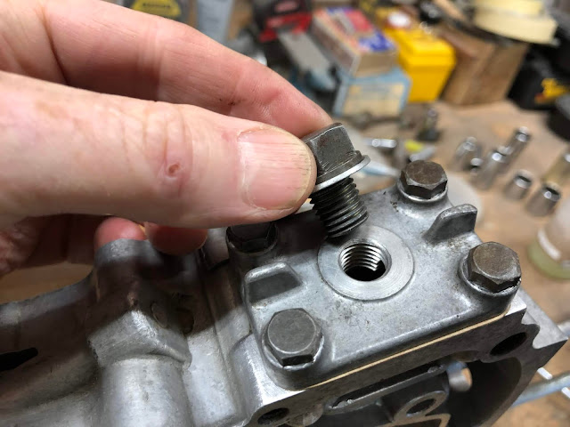

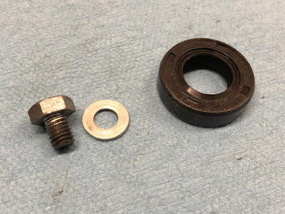
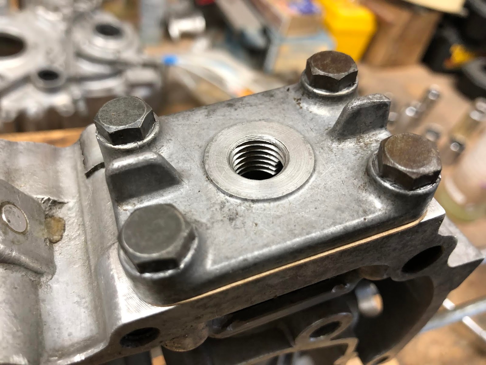
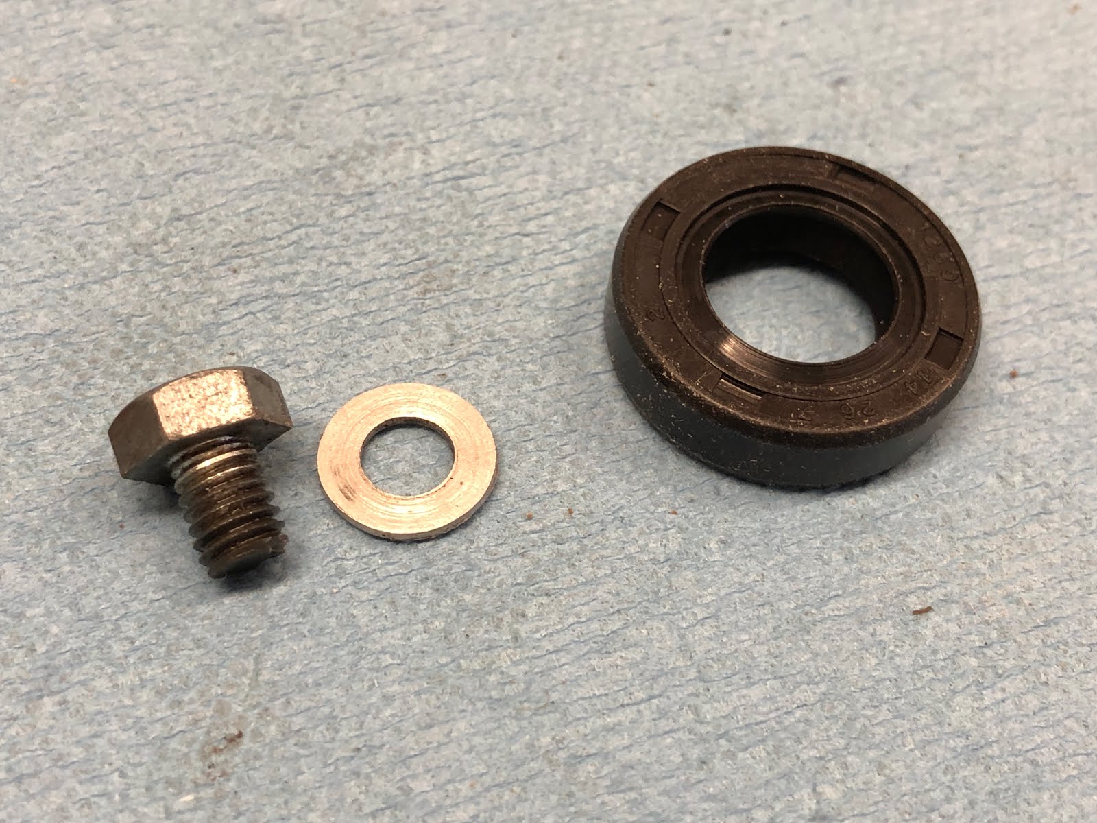
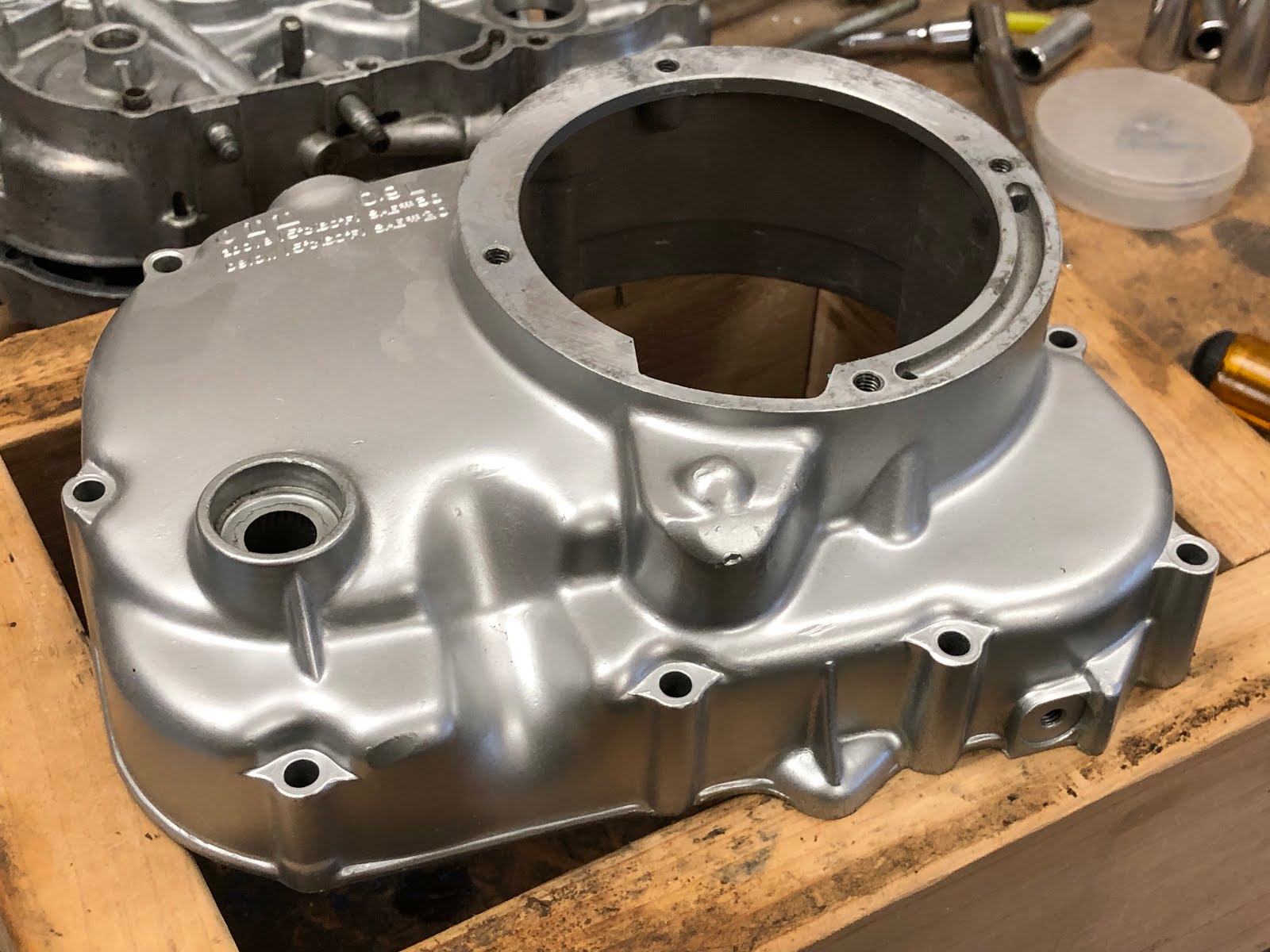
Next I move on to the clutch case side cover to install the seal for the kick start shaft and also the small drain plug near the front of the cover.

First I'll install the small bolt and aluminum crush washer that is the seal for the bolt.

These go in the threaded hole on the bottom of the cover towards the front.


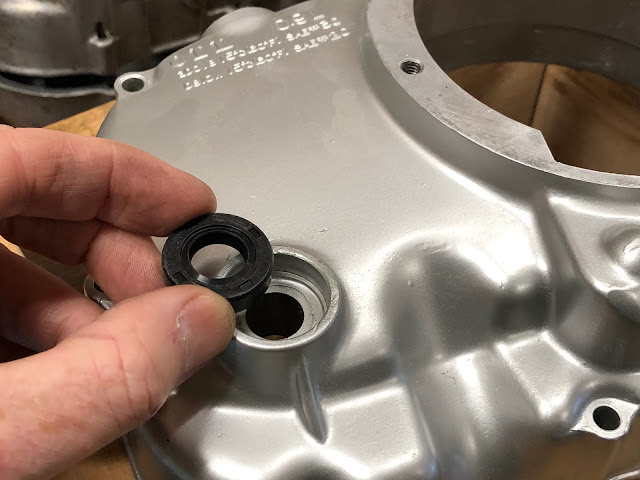
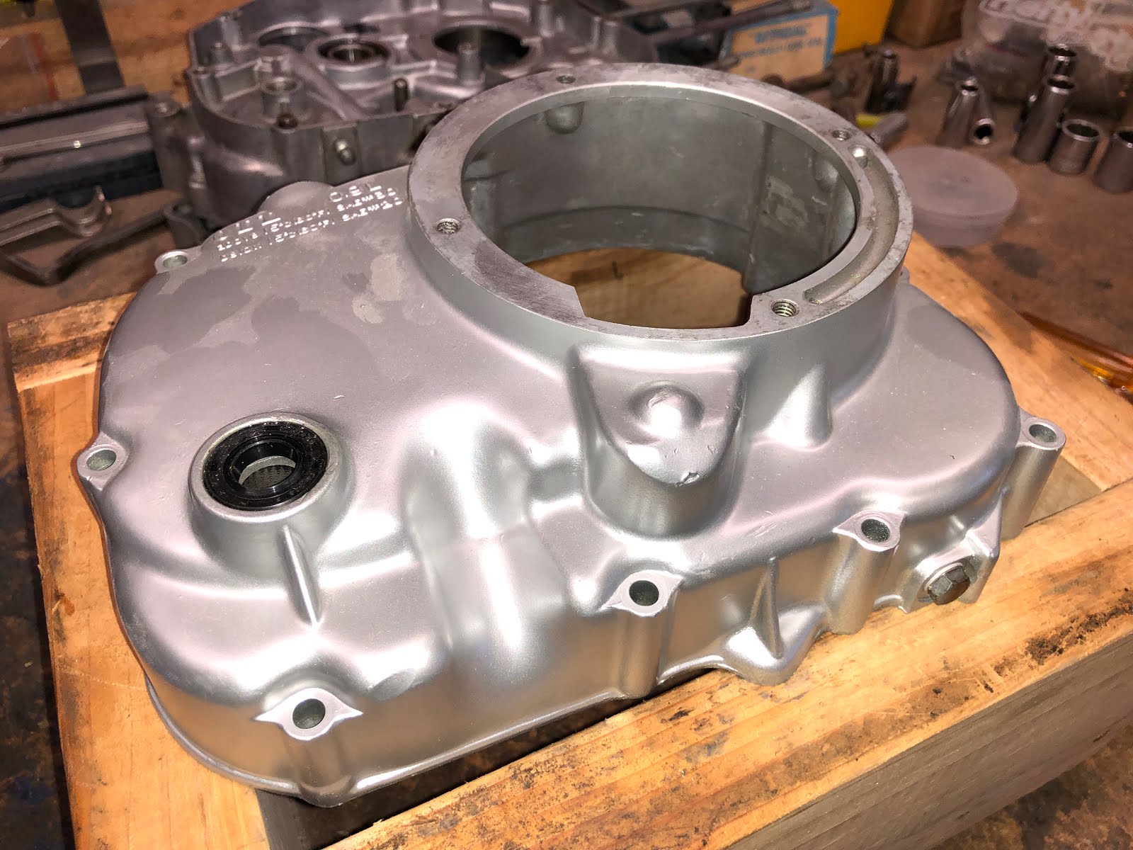
Next we'll install the seal for the kick-start shaft following the same approach as was used with the other seals installed earlier.

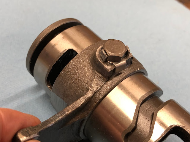
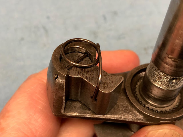
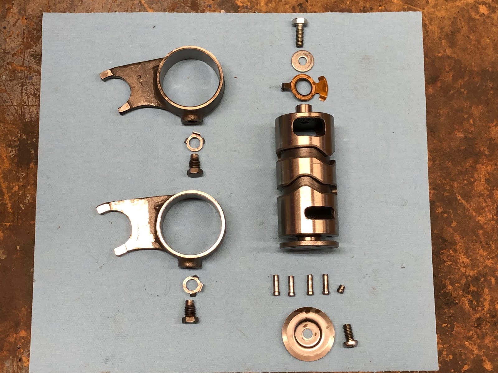
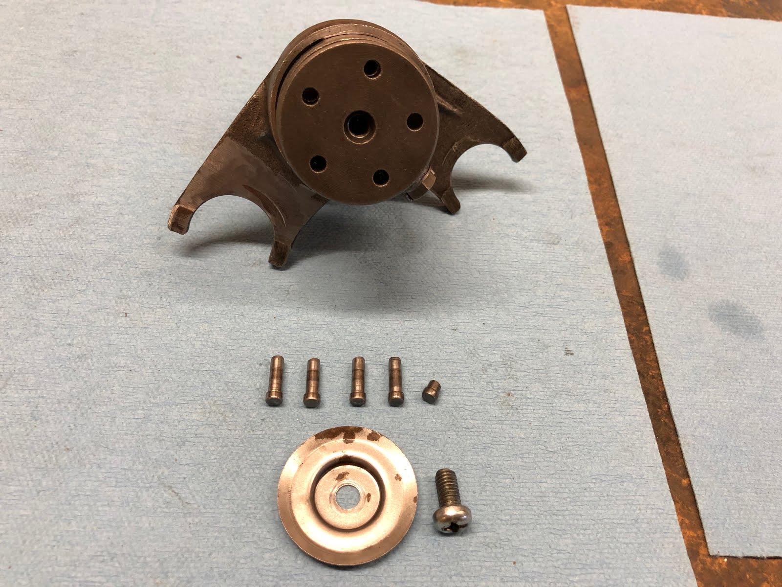
The next step is to build up the sub assemblies that make up the transmission and I'll start with the shifting fork assembly which includes the parts in the picture below. Some people may not disassemble this assembly, but I always do just to make sure and get all of the crud out of the nooks and crannies.

The first step is to install the shifting fork on each end of the assembly with the small width fork installed from the end with the short stub shaft and the wider shift fork installed from the end with the plate that has five holes.
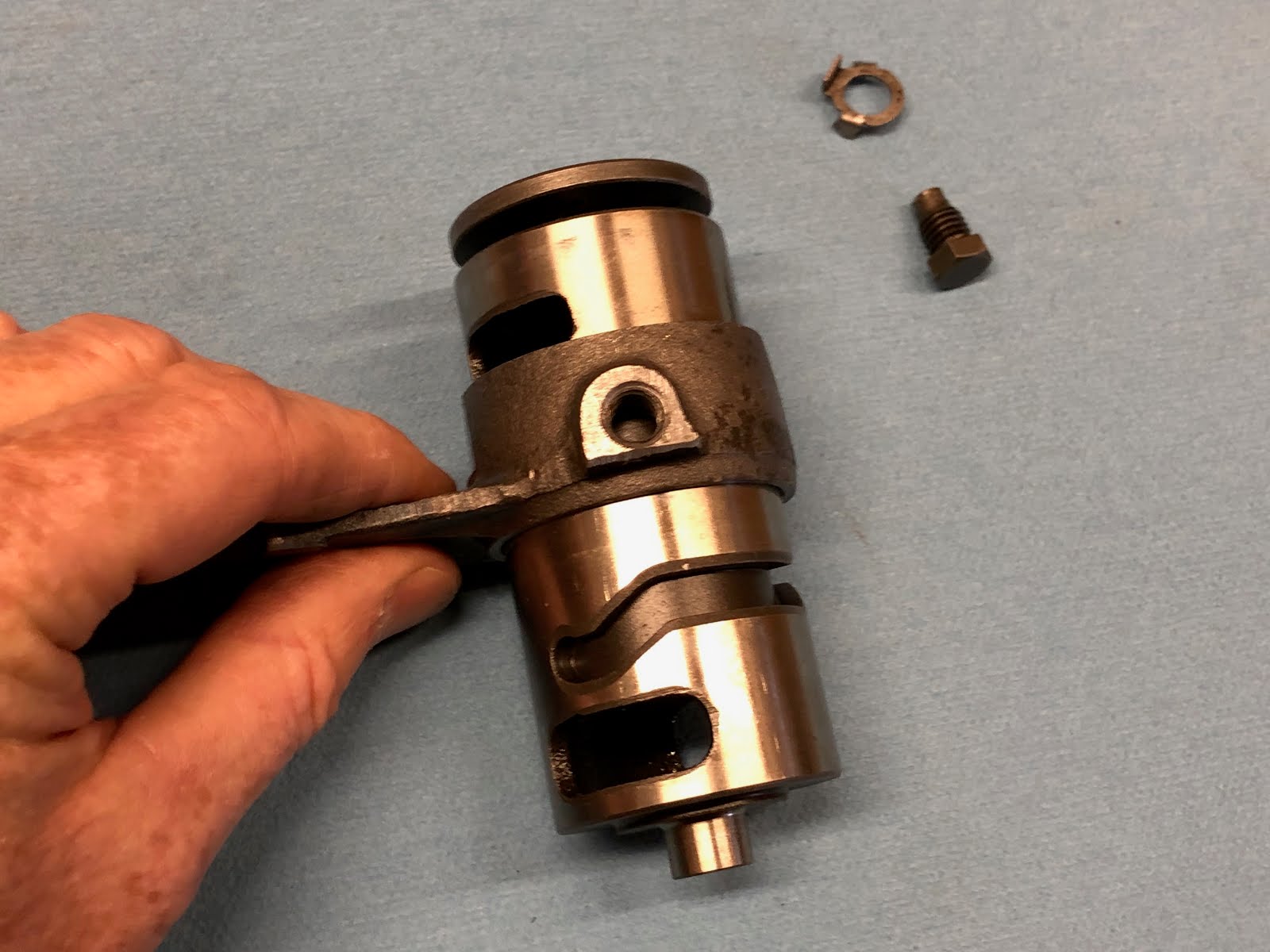
To install the shift fork slide it over the appropriate end until the threaded hole is over the slot on the shift drum that runs around most of the diameter of the shift drum.


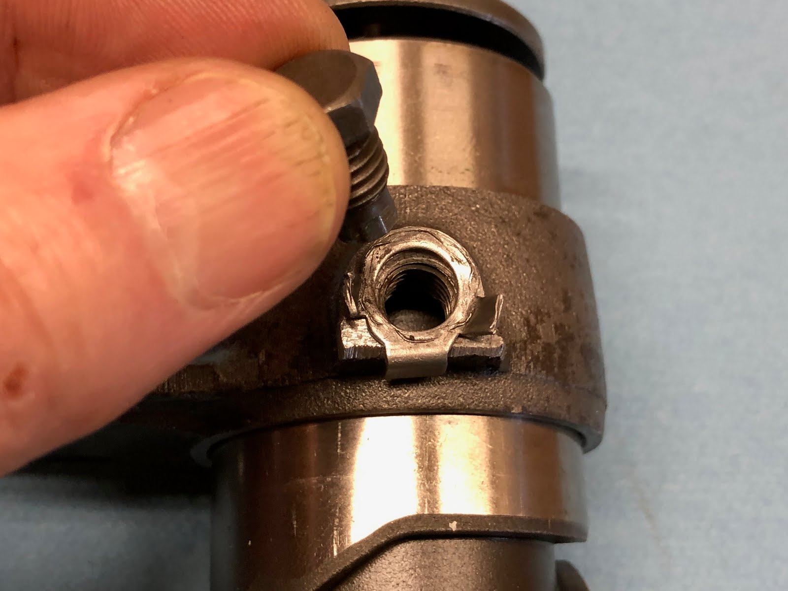
Next place the washer with the locking tabs over the threaded hole making sure the larger tab is engaged with the straight edge of the raised boss of the threaded hole and then install the special bolt and tighten.


With the bolt tightened, fold up the tabs on the washer against the flats of the bolt head to lock it in place.
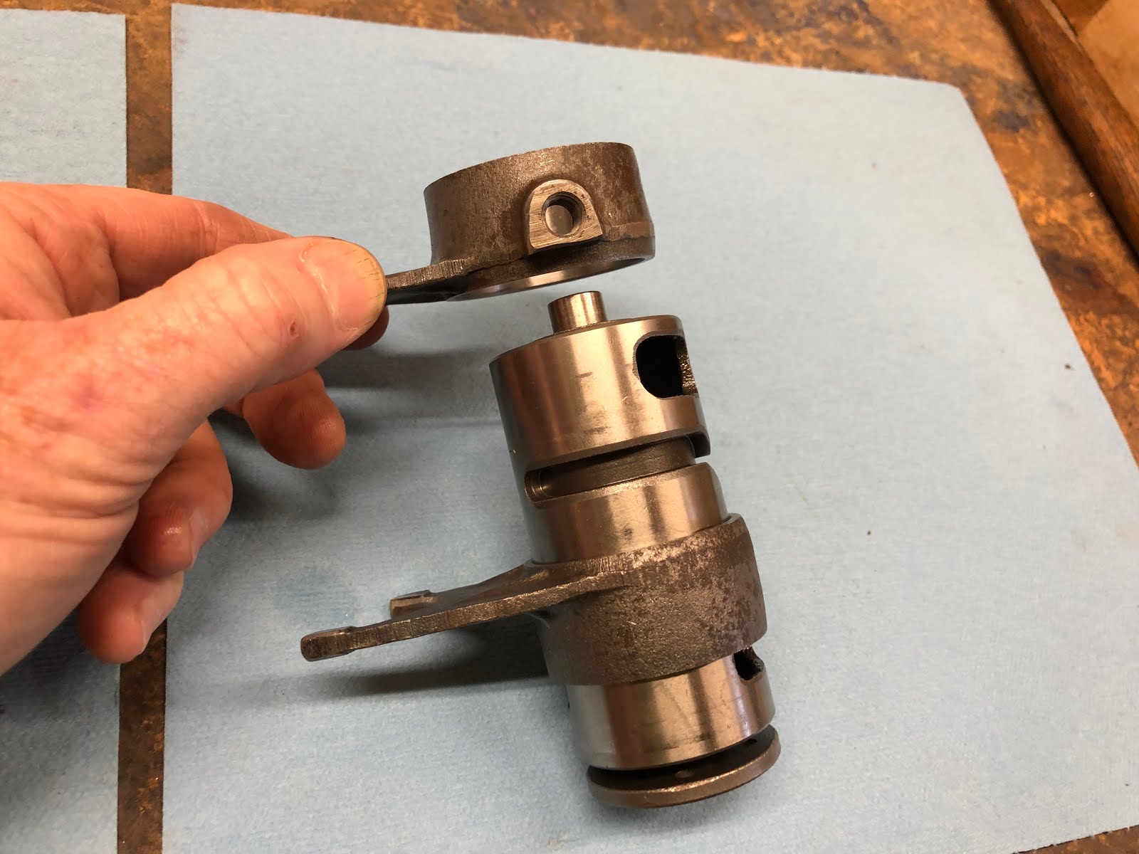
Now repeat the same steps to install the other shift fork on the other end of the shift drum as shown below.


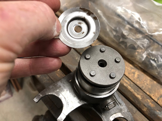
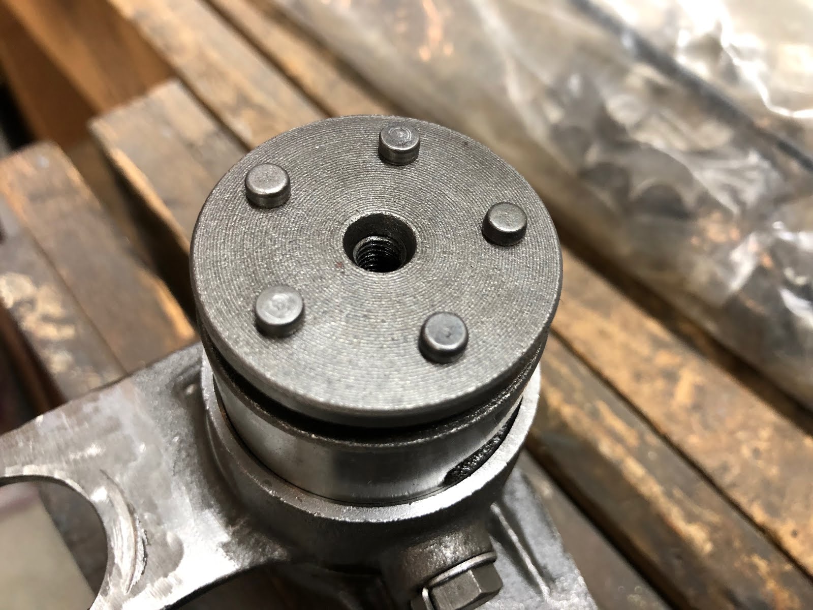
The next step is to install the headed pins and the retainer plate on the end of the shift drum.
If you are missing any of the pins here are their dimension in inches.
The head on all of the pins is .194 inches in diameter and .106 inches long.
The length of the straight section of the four longer pins is .475 inches long
The length of the straight section of the one short pin is .100 inches long
The diameter of the straight section of both the short and long pins is .055 inches in diameter

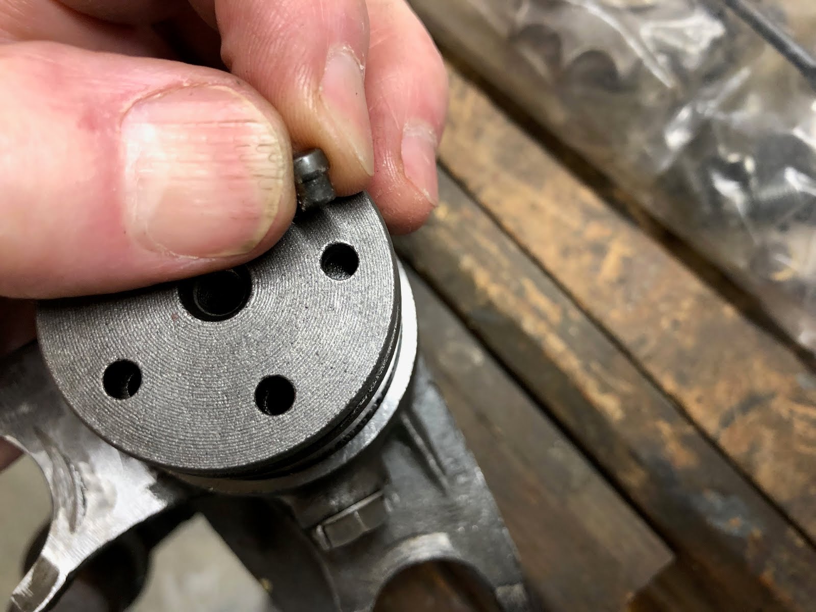
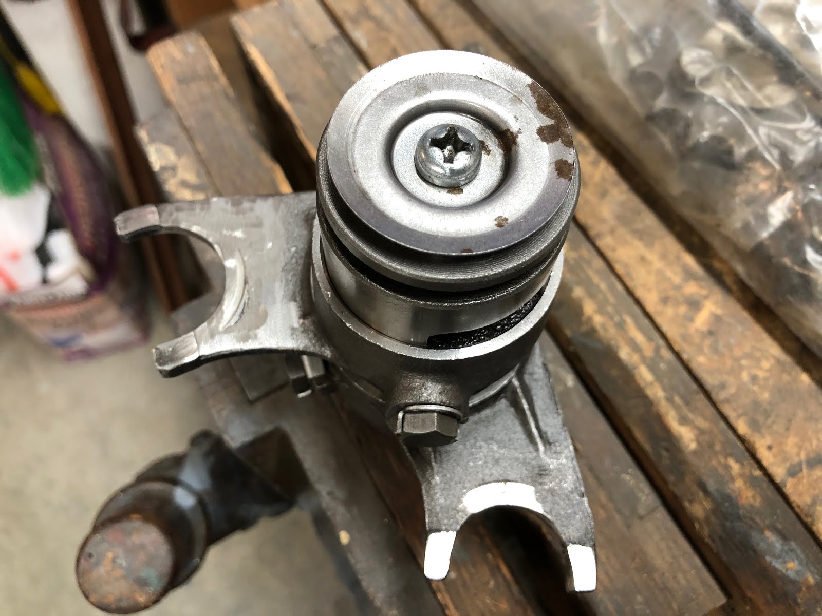
With the five holes on the plate at the end of the shift drum four are deep and one is shallow. When the pins are installed the head of the pin should be setting on the plate, so if you insert the long pin in the shallow hole it will protrude out which is incorrect as shown in the picture below.

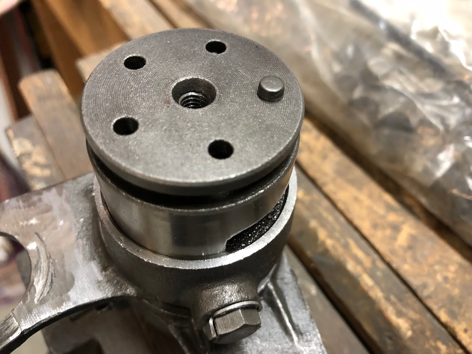
Install the short pin in the shallow hole and then proceed to install the remaining four long pins as shown below.


The next step is to install the plate and screw that retain the pins.
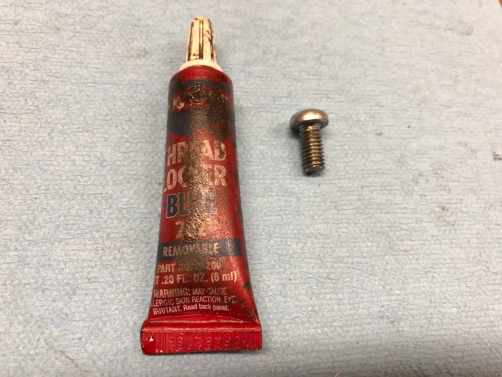
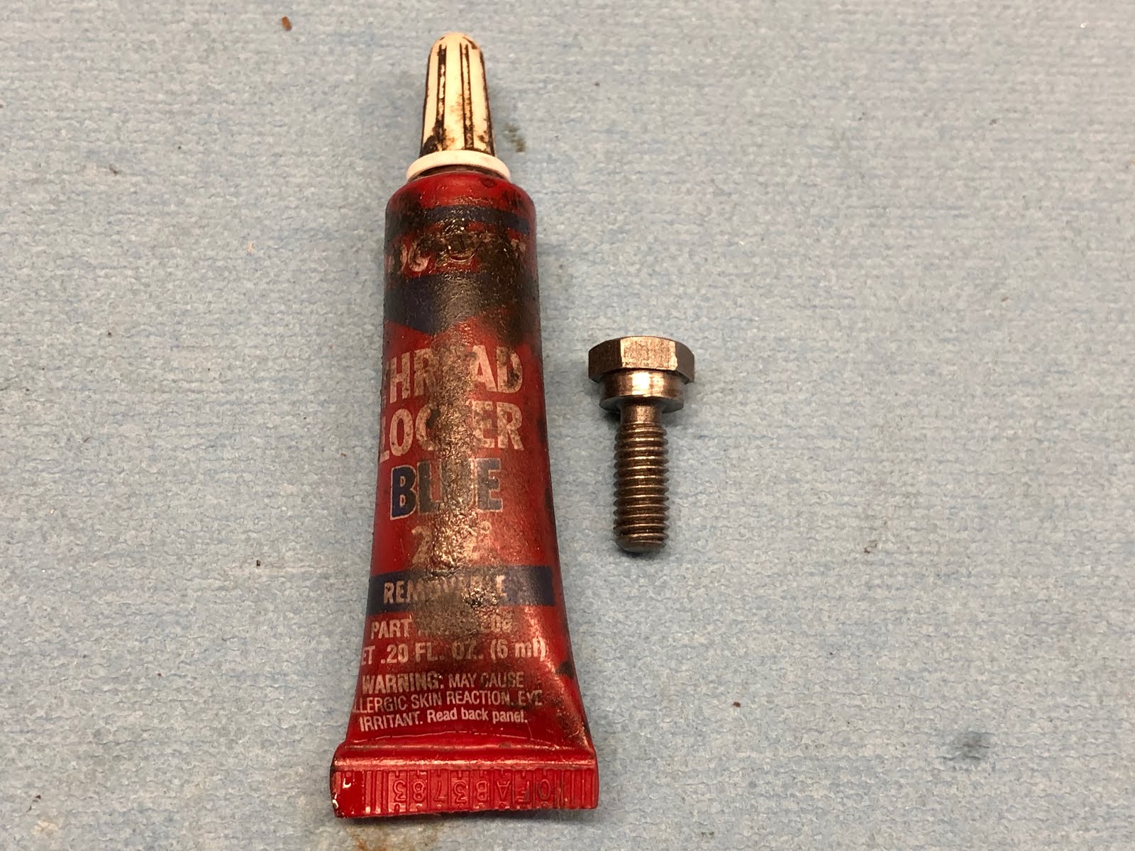
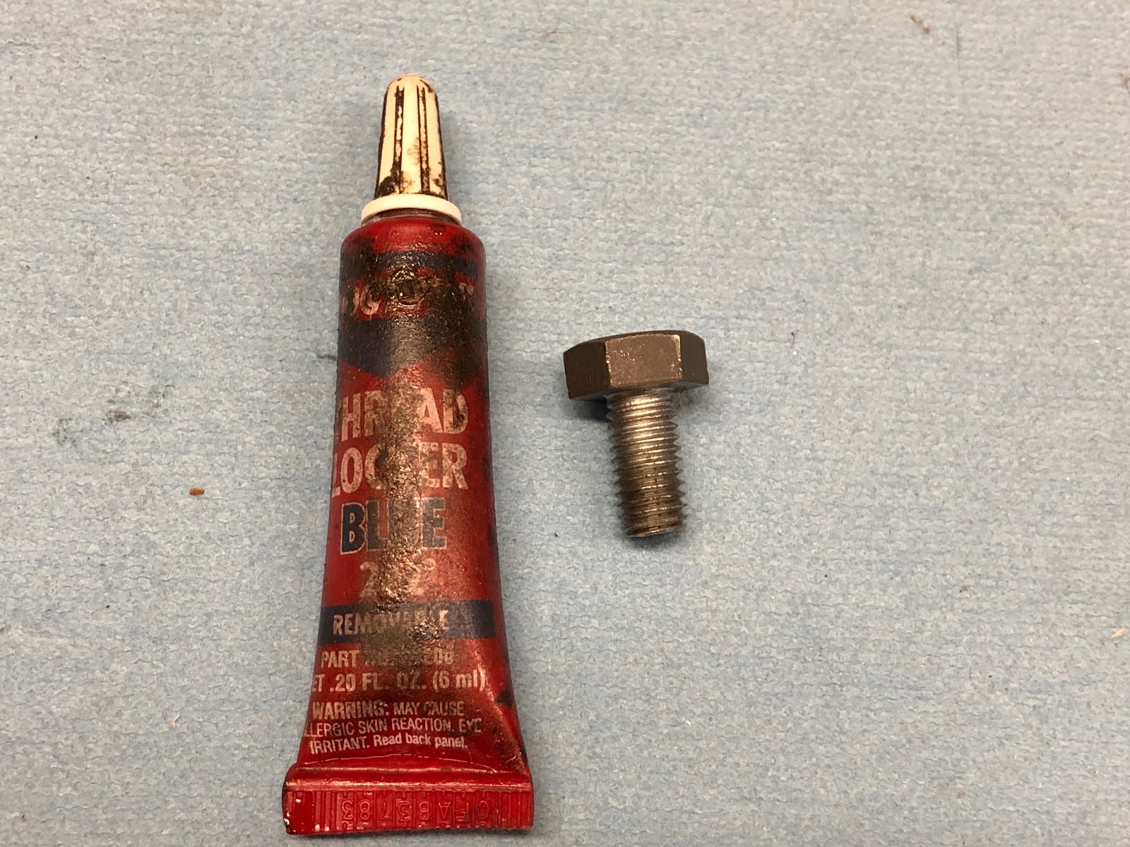
I apply some blue Loctite to the screw to help make sure the plate won't come loose.


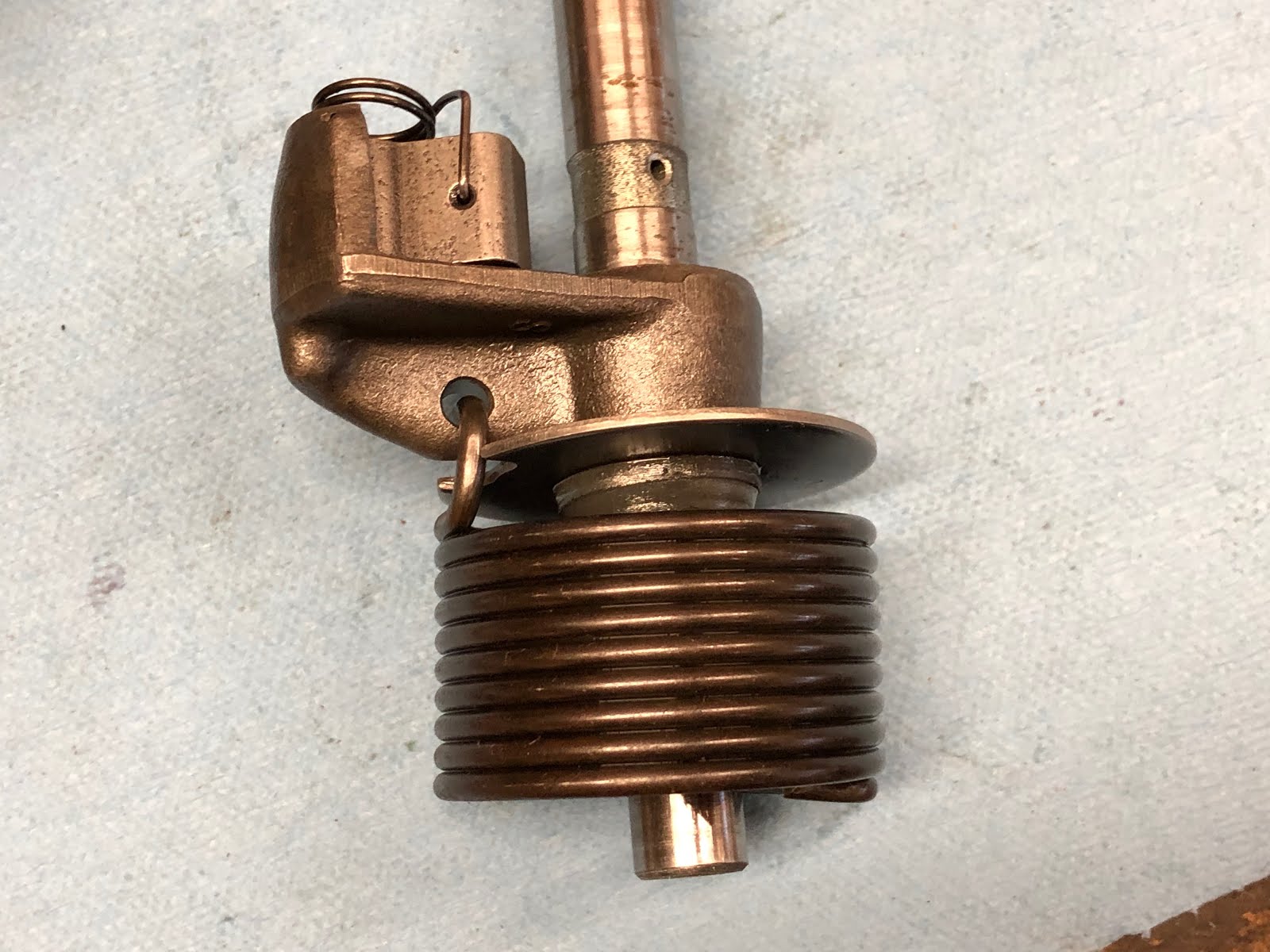
The last step for this assembly is to install the copper component that provides a ground to the neutral light.

To install this component it is slipped over the small shaft on the end of the shift drum while aligning the hooked end with the small hole on the same end of the shift drum.

And then gently work the hook down into the hole until the copper component is seated at the base of the shaft as shown below and then this assembly is complete. While I didn't do it hear, this would have been a good time to clean any oxide off the copper component to help ensure you always will have a good ground for your neutral light.

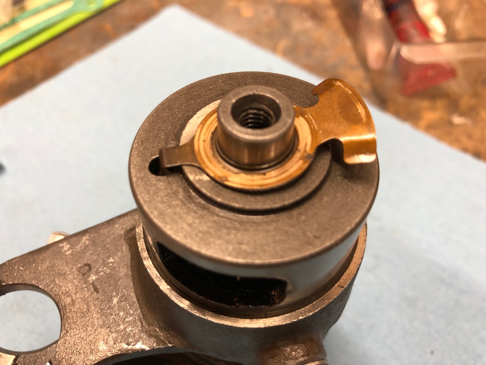
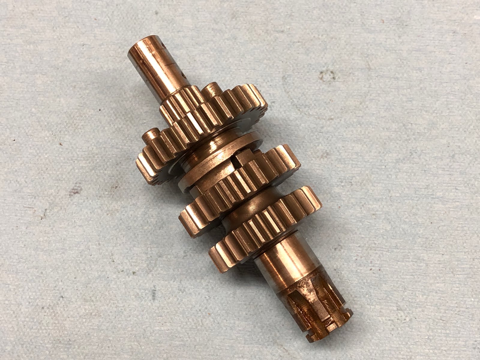
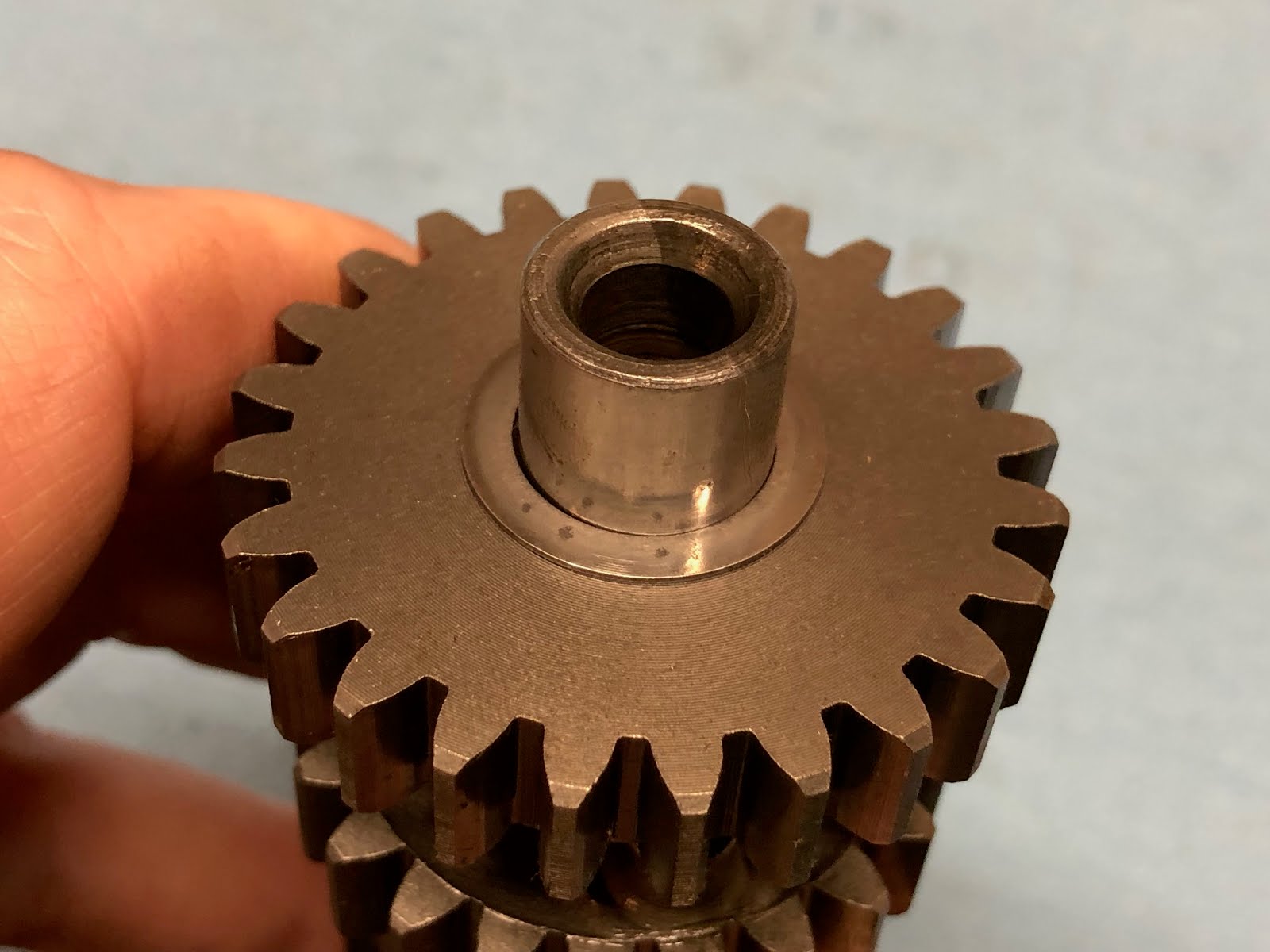
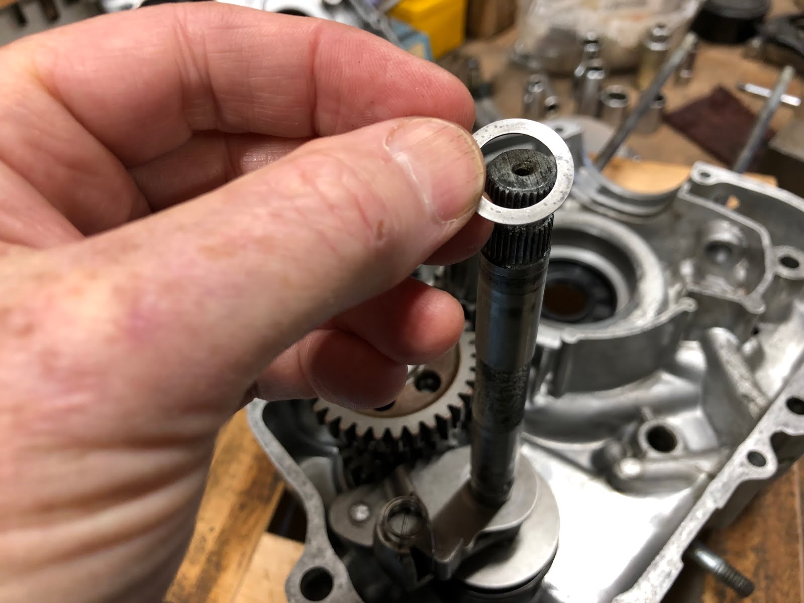
The next step is to assemble the two gear and shaft assemblies that make up the transmission.
Here are the components that make up the first assembly that contains the shaft with the interface that will ultimately accept the chain drive sprocket.

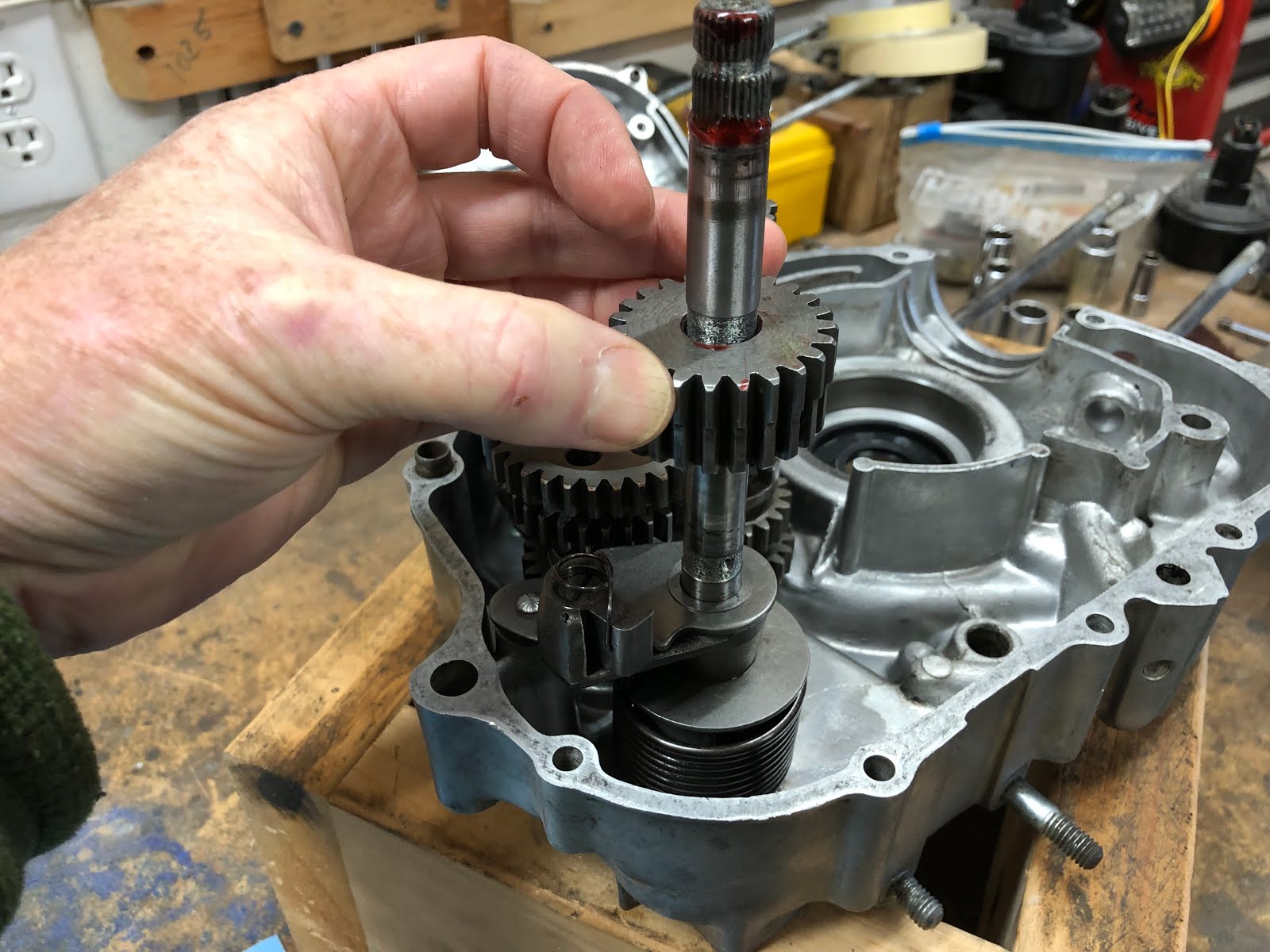
These components assemble in a straight forward manner with the intermediate slid down the shaft with the square dogs mating with the square dogs on the gear that is already on the shaft assembly.

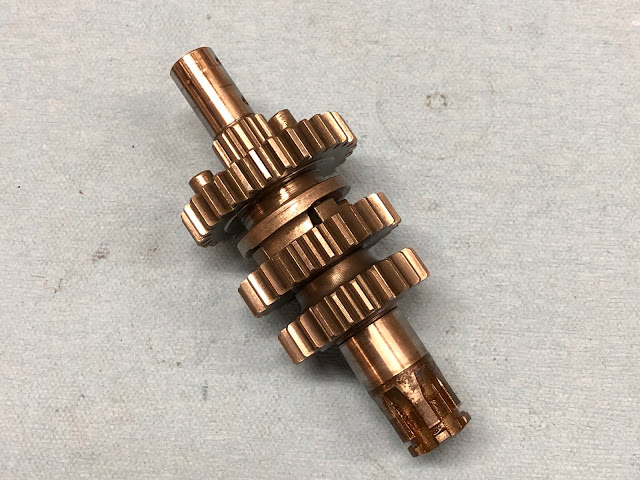
Next the remaining gear is slipped down on the shaft facing the pins on the gear that was just installed. This gear is symmetric and can be installed either way.

Lastly the thrust washer is slipped over the end of the shaft.
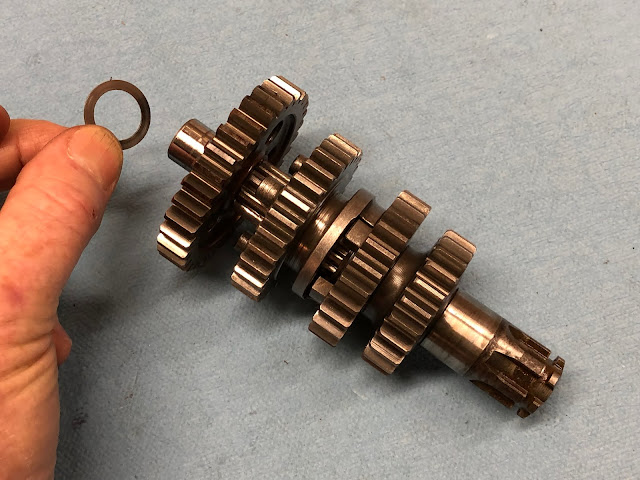

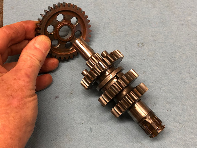
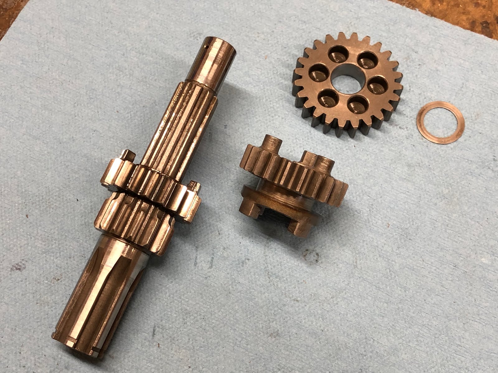
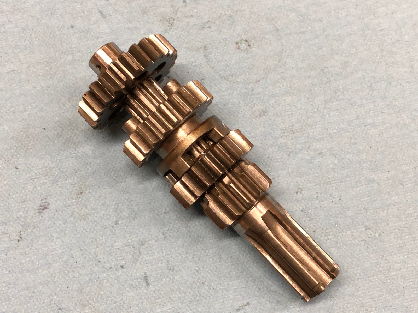
Here are the components that make up the second shaft assembly.

This is assembled in the same manner as the previous assembly with the square dog end of the intermediate gear facing the square dogs on the gear that is part of the shaft assembly.


The last gear to be installed is not symmetric and must be installed with the side that has bottomed holes facing the pins on the gear that was just installed.


The last step is to install the thrust washer on the end of the shaft. You can add a little assembly lube to one side of the thrust washer to help it stick to the last gear that was installed as the washer will be facing down and potentially come off when this assembly is finally installed in the engine housing.


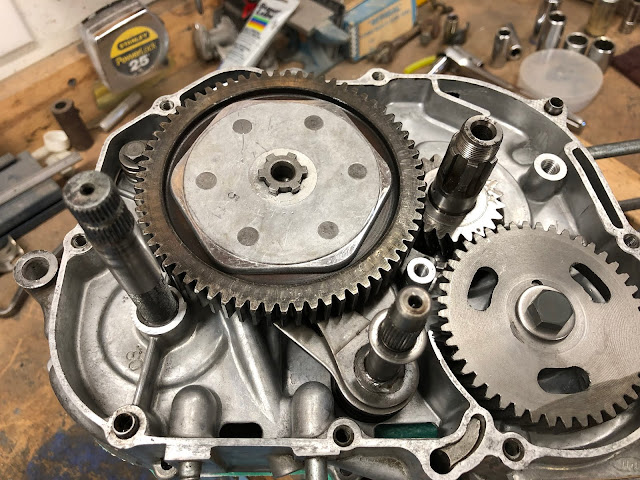
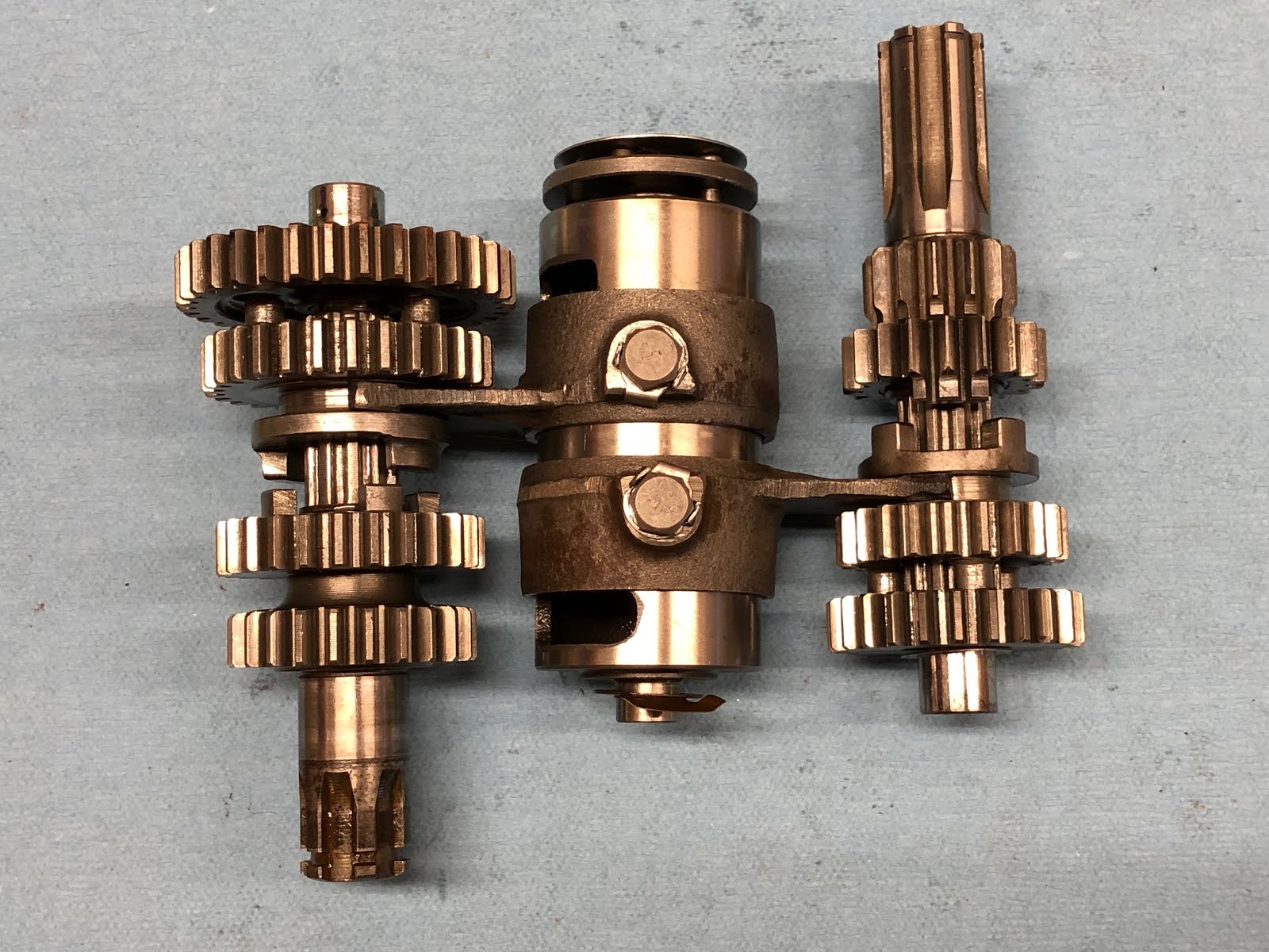
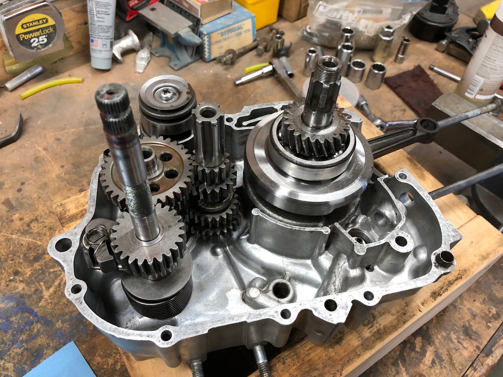
The next step is to assemble the two shaft assemblies to the shift fork assembly as shown in the picture below.

The two shaft assemblies are rotated towards each other while remaining engaged to the shift forks as shown below (the one lower gear at the end of the shaft slipped downbeat was moved back to its correct position when it was installed into the engine housing).

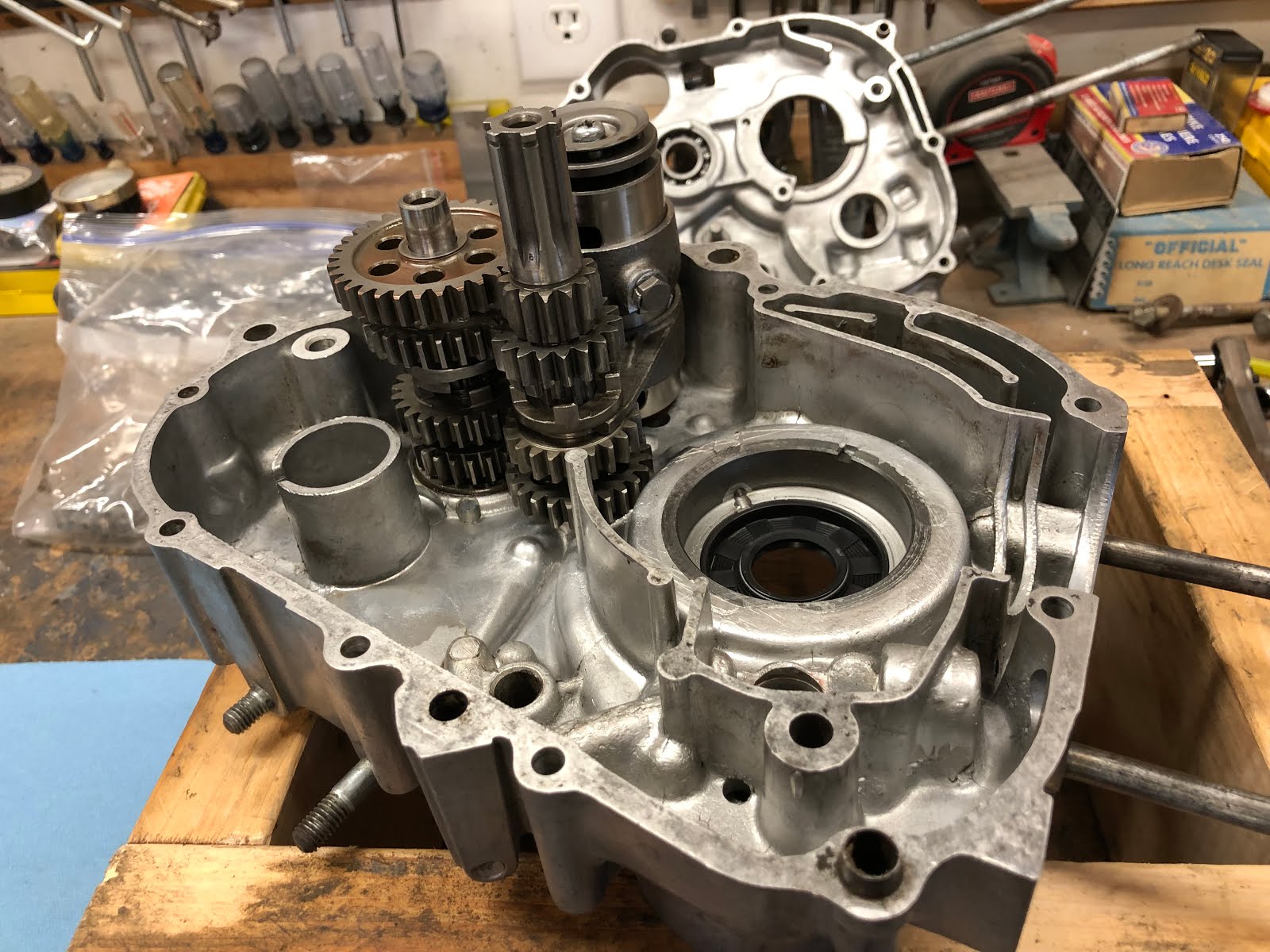
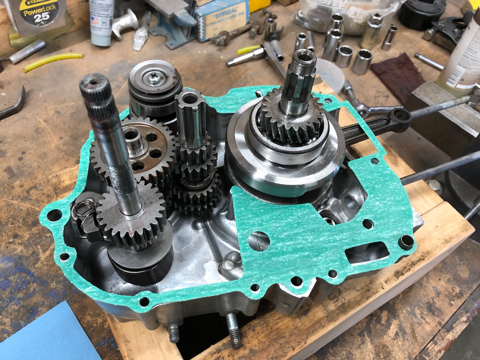
The collection of assemblies are then installed into the left center engine housing as shown below.


The next step is to install the components that make up the kick starter assembly.

The first step in building up this assembly is to install the pawl into the pocket as shown below and then spring that actuates the pawl.

The next step is to install the large spring on the assembly

The next step is to install this assembly into the left center engine case so the the tang on the large spring engages the slot in the housing as shown below.

The next stem is to install the plate with the positioning pin down over the kick starter shaft and then you will have to rotate the shaft assembly that was just installed counterclockwise slightly so that the pin in the plate can engage the hole in the housing and be set down in its final position as shown below.

Next one of the two thrust washers is installed down over the lick starter shaft

This is followed by the installation of the gear and then the last thrust washer


The next step is to install the crank assembly.
The crank drops into the center left engine housing as shown. You might apply a little oil to the lip of the seal that the crank will be passing through to help it more easily slip over the shaft feature the seal will be running on.


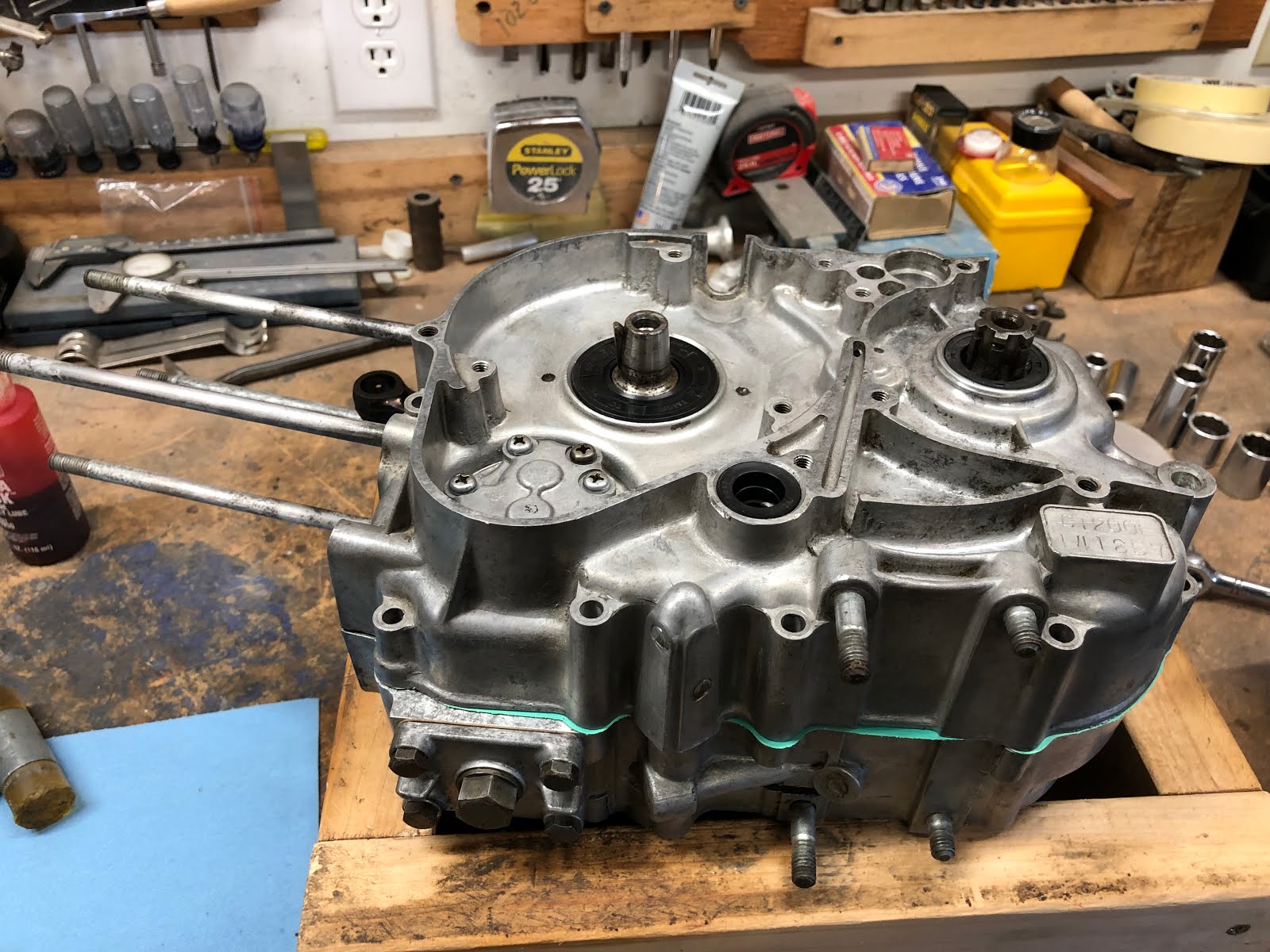
The next step is to install the gasket that goes between the two housings and then install the right side center housing.

Sometimes a few very light taps of a plastic hammer can help the housing settle down over the guide bushings and the crank. When using a plastic hammer its the light vibration of the taps that help everything seat and you don not want to apply any hard blows that could potentially damage any components.

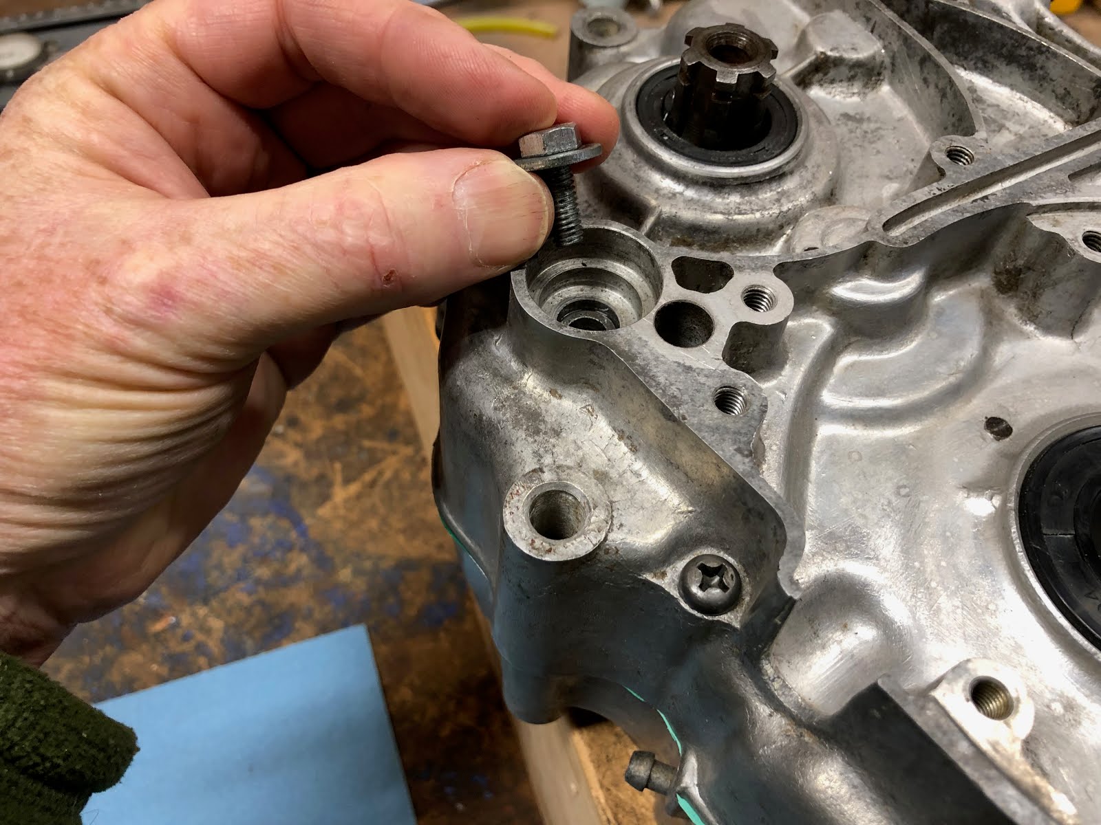
To install the screws that hold the two cases together you will have to flip what you have already assembled while holding the cases together.

Next install the screws that hold the two cases together and torque to the specified value.

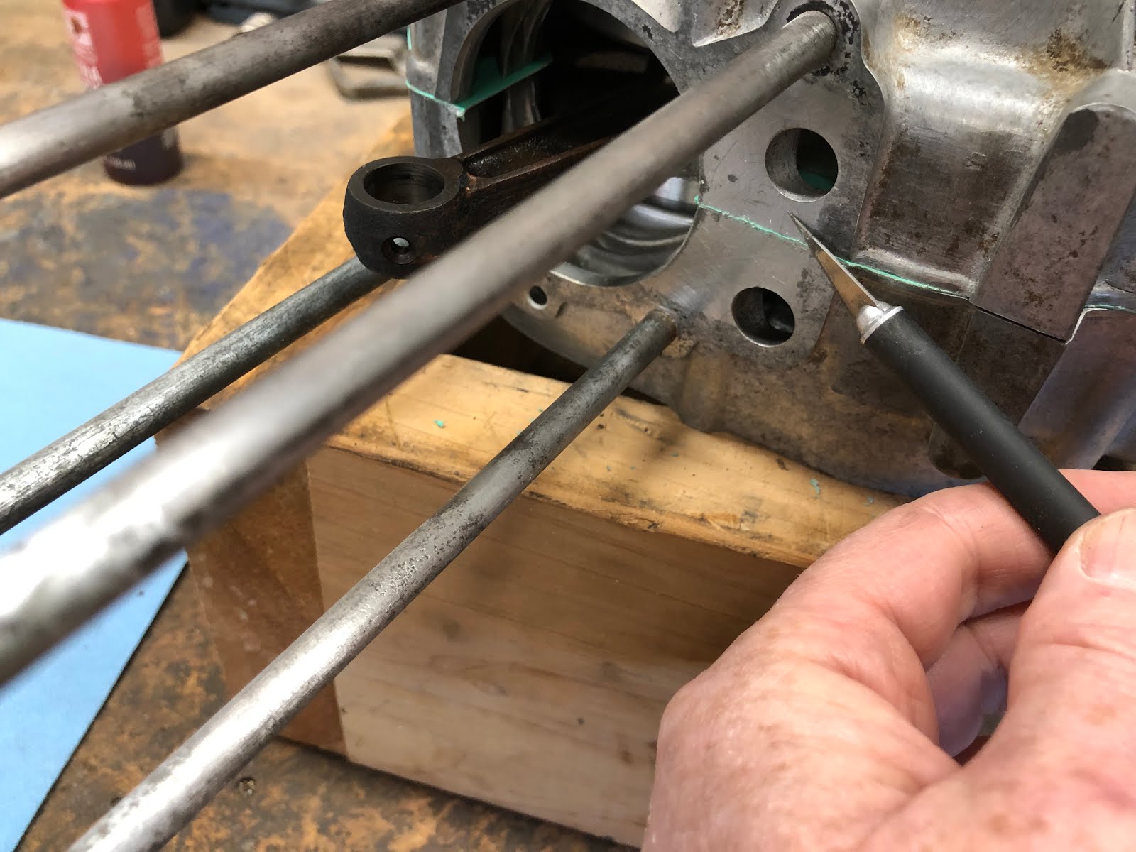
This is a good time to also trim the excess gasket at the interface where the cylinder will seat.

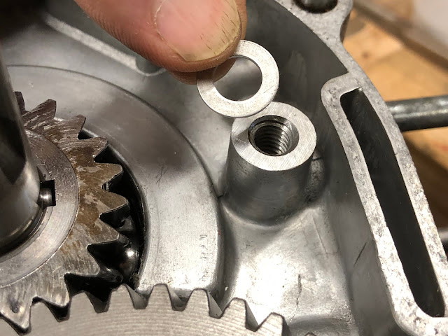
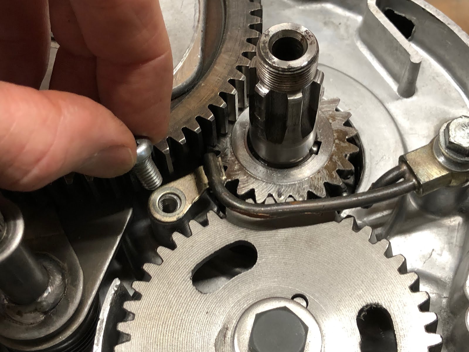
The next step is to install the bolt that retains the shift fork assembly. Depending on how you like to do things this good have been done earlier if desired.

To get the bolt started you may have to push up on the other end of the shift fork assembly.

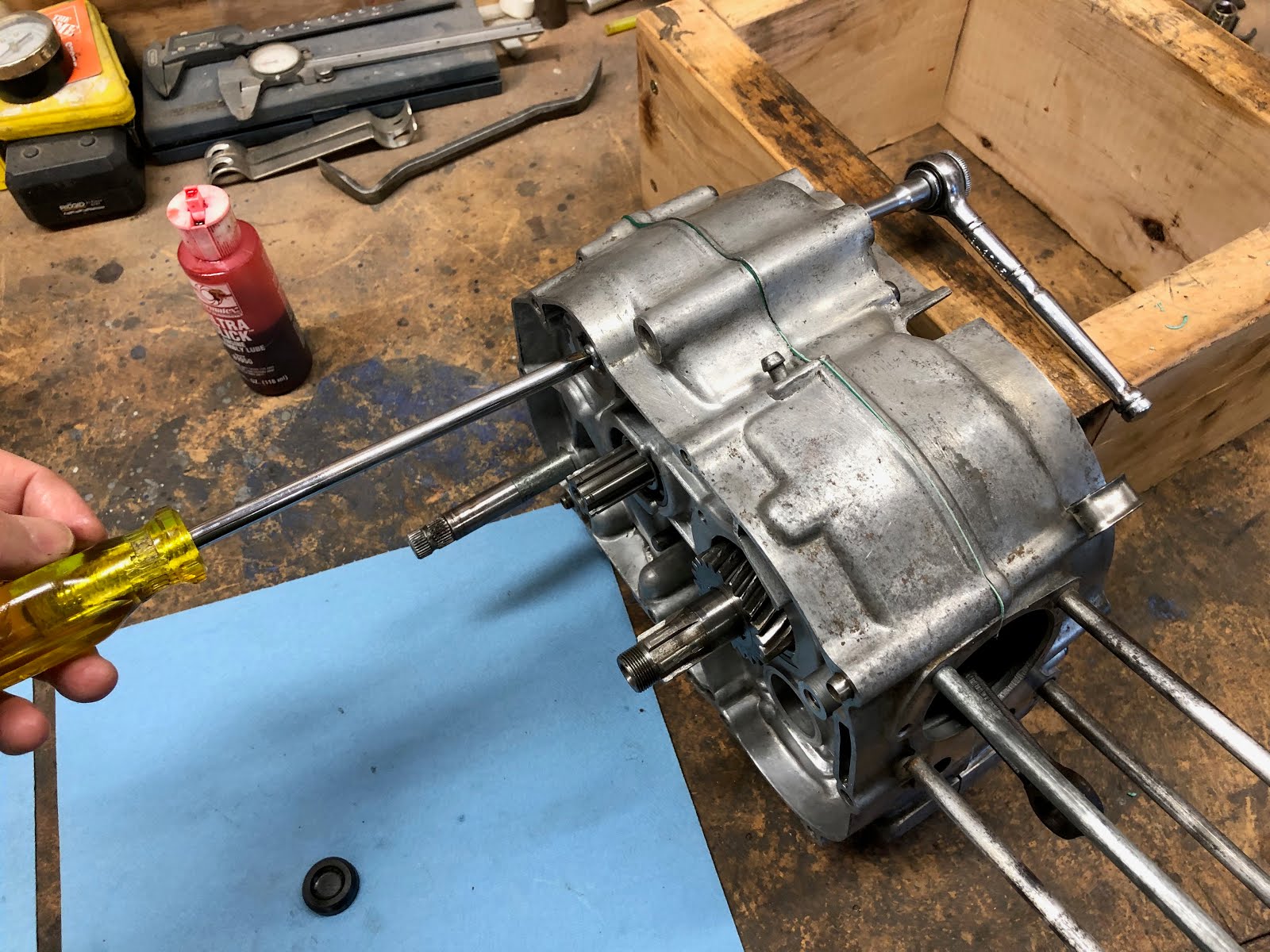
And then to tighten down on the bolt the engine may have to come off the wood stand so that a large screw driver can be installed into the screw on the shift fork assembly that holds the pin retainer plate as shown below.

The last step is to install the rubber plug that covers the bolt that was just installed and it is simply placed over the hole and tapped into place.

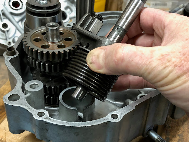
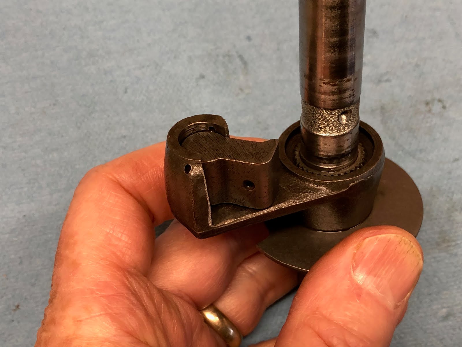
The next step is to assemble and install the components that make up the gear shift shaft and the shift drum stopper.

The first step is to install the small spring on the arm that interfaces with the shift drum.

Next the arm assembly is slid down on the gear shift shaft and secured with a retaining ring as shown in the following pictures.
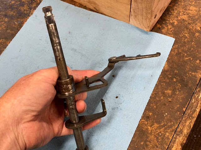
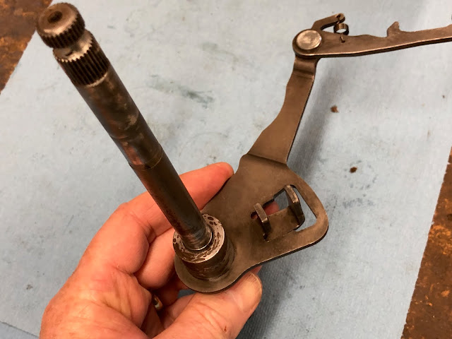


The next step is to install the large spring as shown in the photo below.

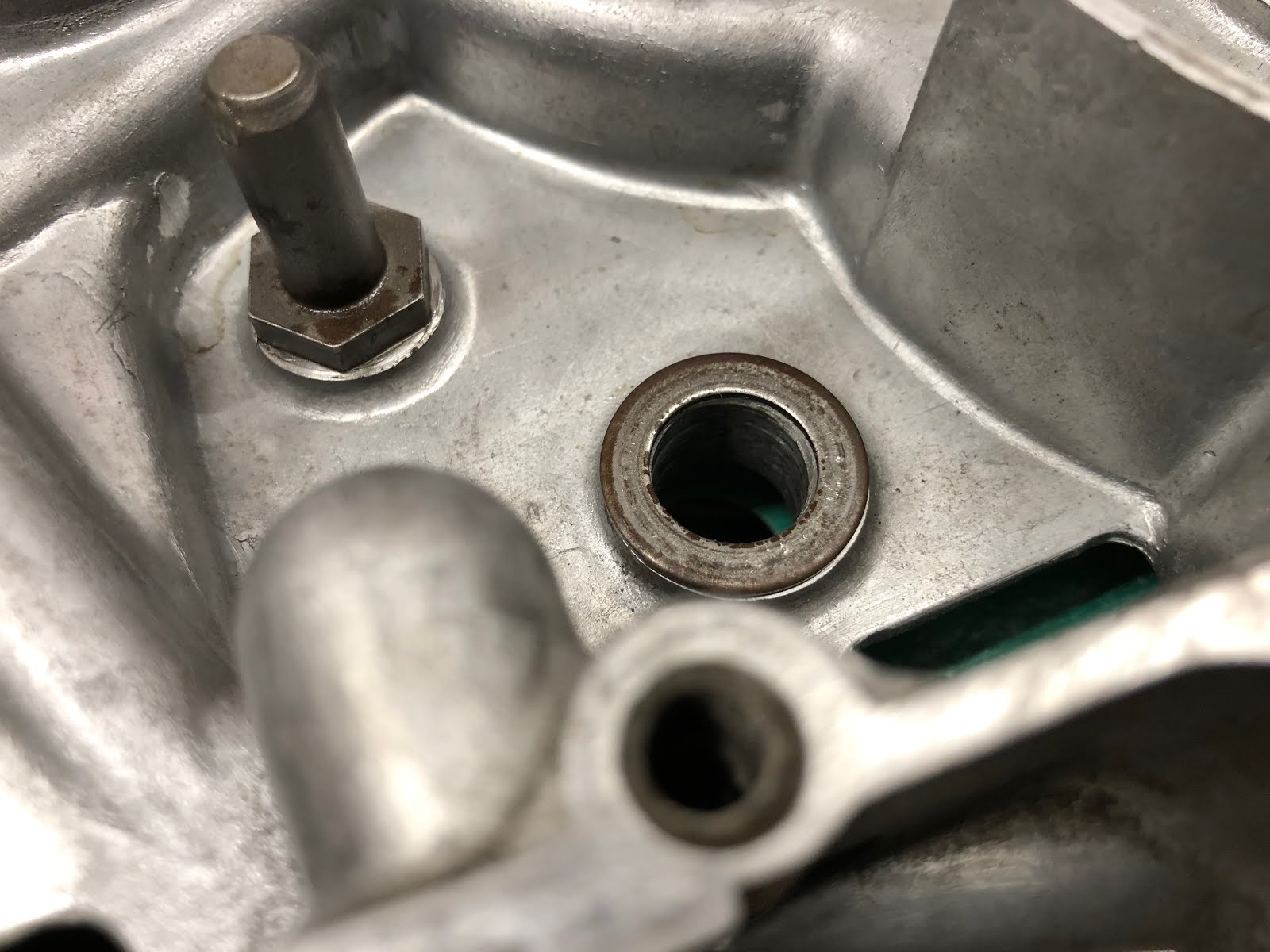
Before the gear shift shaft assembly can be installed in the engine the thrust washer needs to be placed over the hole the shaft will be installed into.


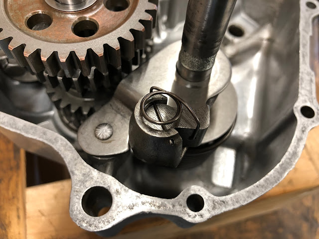
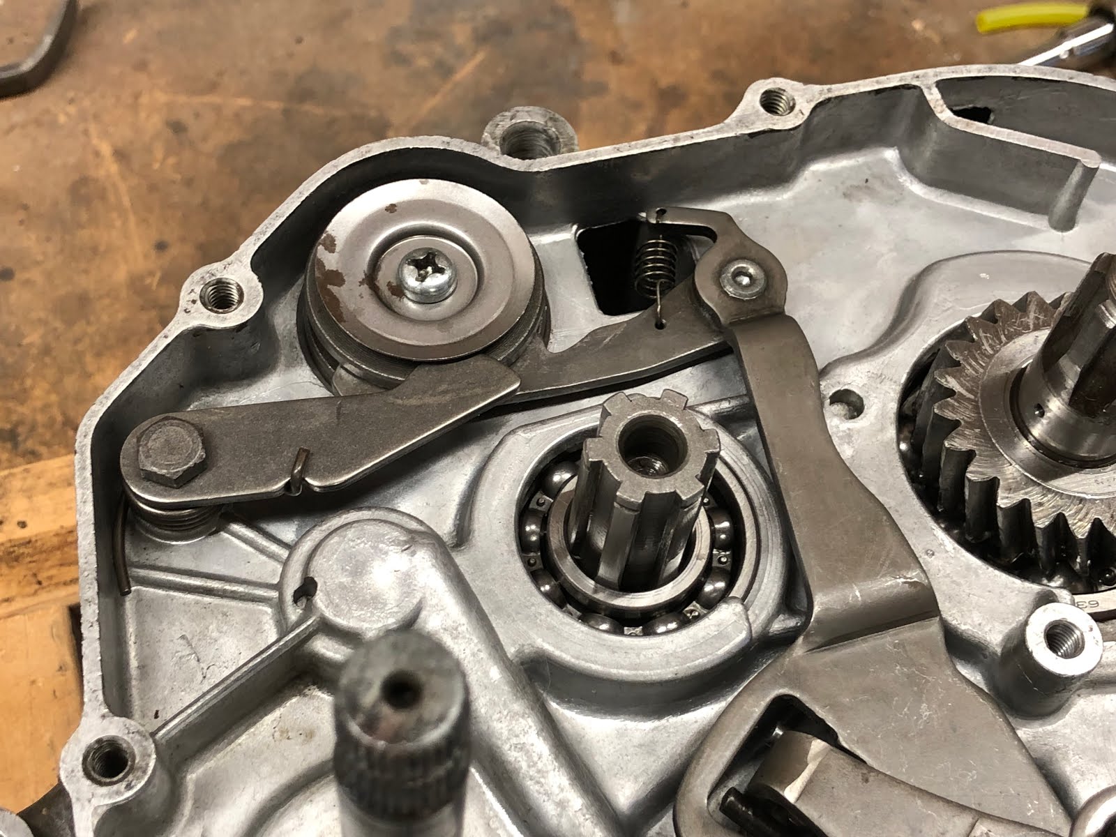
Next the gear shift shaft assembly is installed into the hole and slide down until it rests on the housing and then the arm is engaged in the slot with the pins on the shift drum as shown in the pictures below.

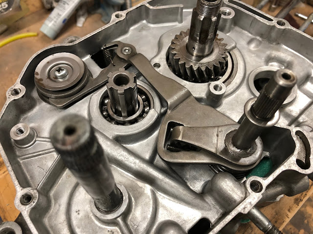
To install the shift drum stopper the spring is attached to the stopper and then stopper is placed in position and the special bolt is installed using blue Loctite as shown in the pictures below. The shift drum stopper ends up ridding on the head of the pins in the shift drum.


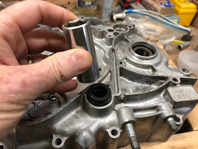
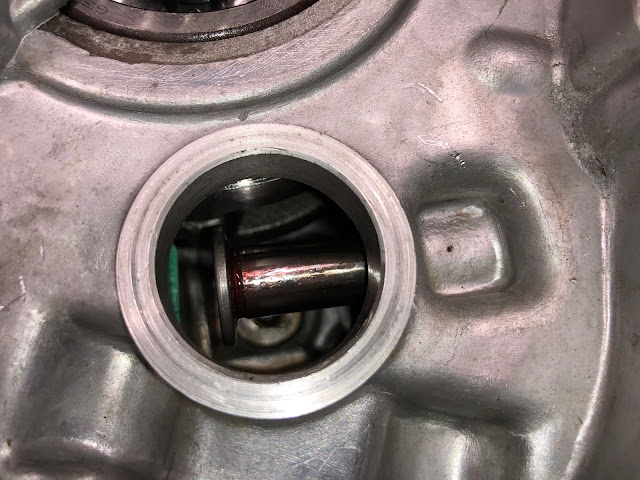
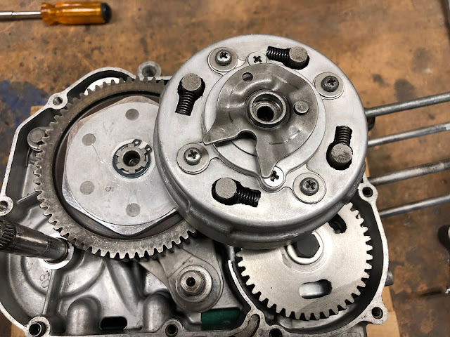
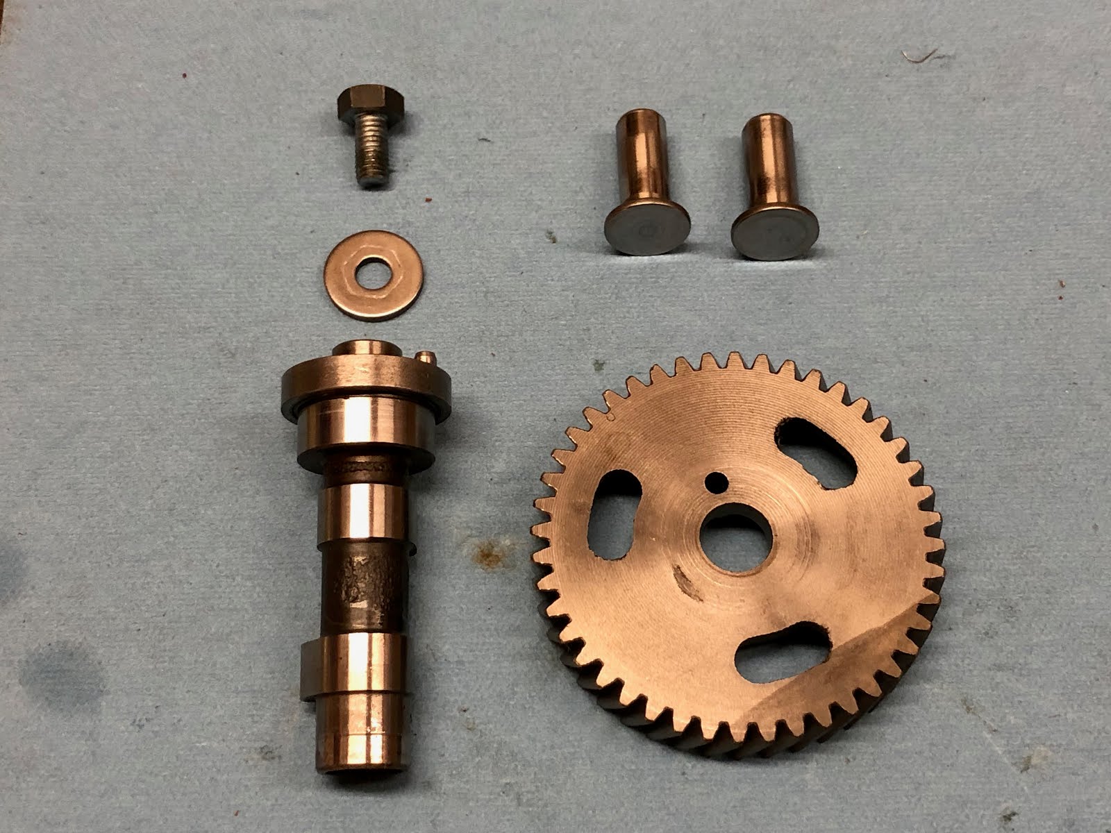
The next step is to install the push rod lifters followed by the cam shaft and timing gear assembly.

The push rod lifters could have been installed earlier when the two center housings were apart, but I chose to wait until now so I wouldn't have to worry about the lifters dropping out of the bores they are installed into while I was handling the engine. It is a little awkward at this step in the process but very doable.
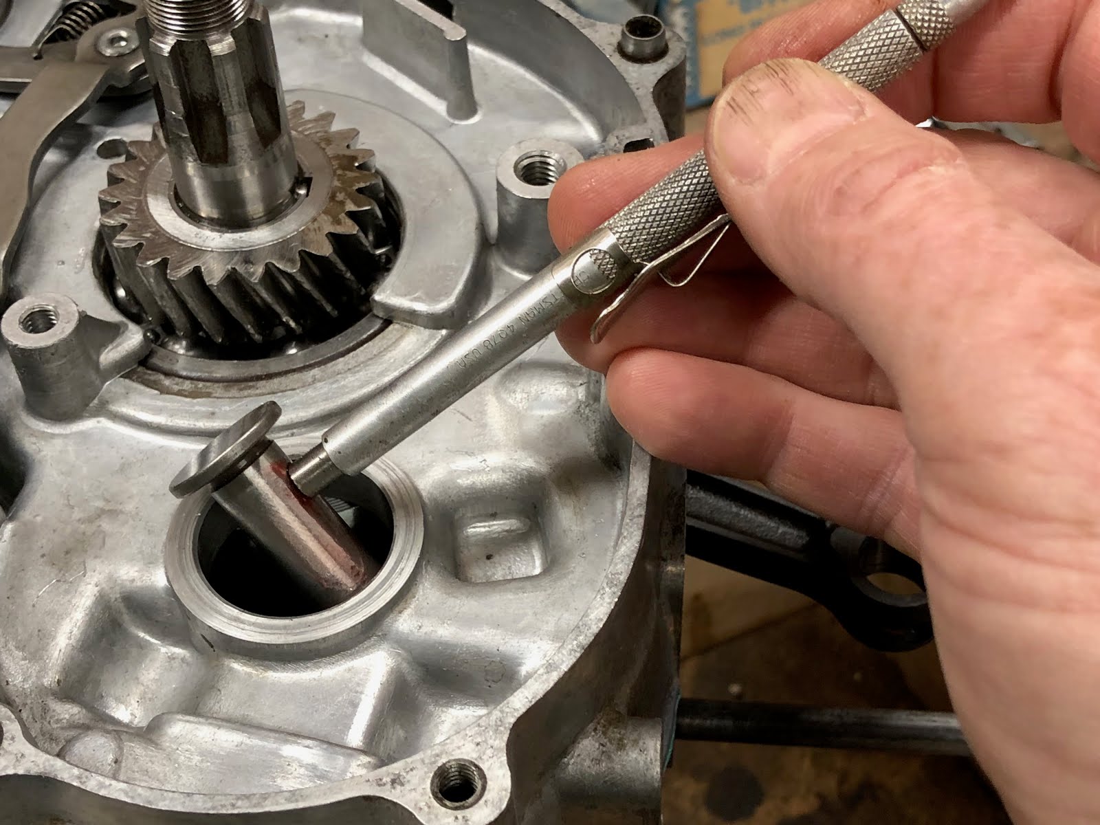
To install the lifters, I will fist add a little assembly lube and the using a magnet I lower each lifter through the opening for the cam shaft and then install one in each of the two bores as shown in the pictures below making sure they are fully seated so they won't interfere with the camshaft when it is installed.


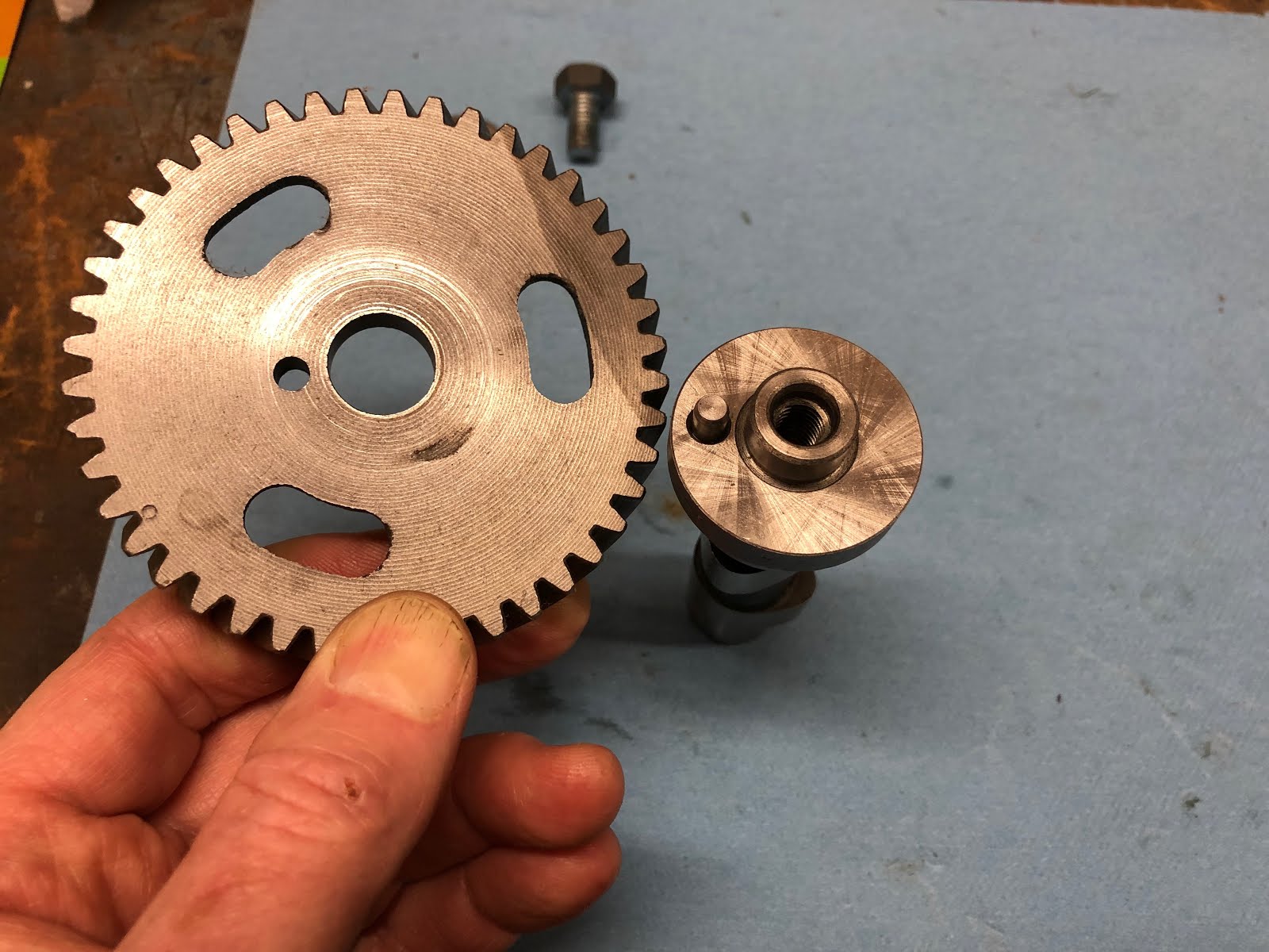
The next step is to install the timing gear to the camshaft. The end of the camshaft that accepts the timing gear has a pin to clock the timing gear to the camshaft. The timing gear is secured to the camshaft with a bolt and washer and its a good idea to add a little blue Loctite to the threads of the bolt.


The next step is to install the camshaft assembly and I'll first apply a little assembly lube to the cam lobes and journals on the camshaft.
When installing the camshaft assembly you have to make sure of two things so the camshaft is installed correctly. The first is to make sure the small pin on the end of the camshaft that drives the oil pump is aligned so that it will pick of the flat drive feature on the oil pump while at the same time you also get the alignment mark on the camshaft timing gear (an "O" stamped between two teeth on the gear) aligned with the timing mark on the crank shaft timing gear.

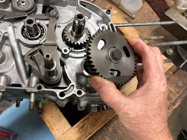
So taking all of the alignment that needs to be done, install the camshaft assembly.
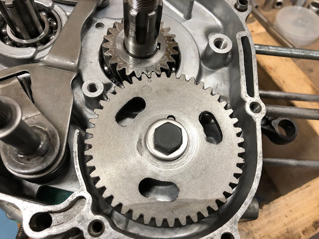
Here is a close up of the two alignment marks on the timing gear after they are installed and this position is also top dead center (TDC).

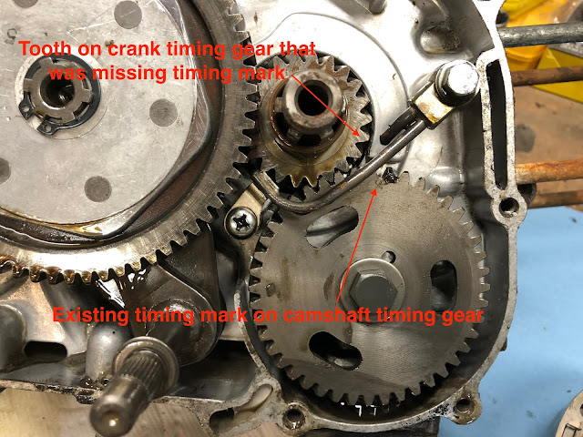
As a side note, when I was initially putting this engine back together I noticed that the timing gear on the crank assembly no longer had a timing mark for whatever reason, so initially I thought I was going to have issues getting the timing gears installed correctly. I then remembered that I had taken photos as I had disassembled the engine and went to the photo below where I was able to identify the tooth on the crank timing gear that would align with the timing mark on the camshaft timing gear. With the picture I was able to look at the stains and other markings on the crank timing gear and go back and identify the appropriate tooth and then I used a center punch to make a new small timing mark.
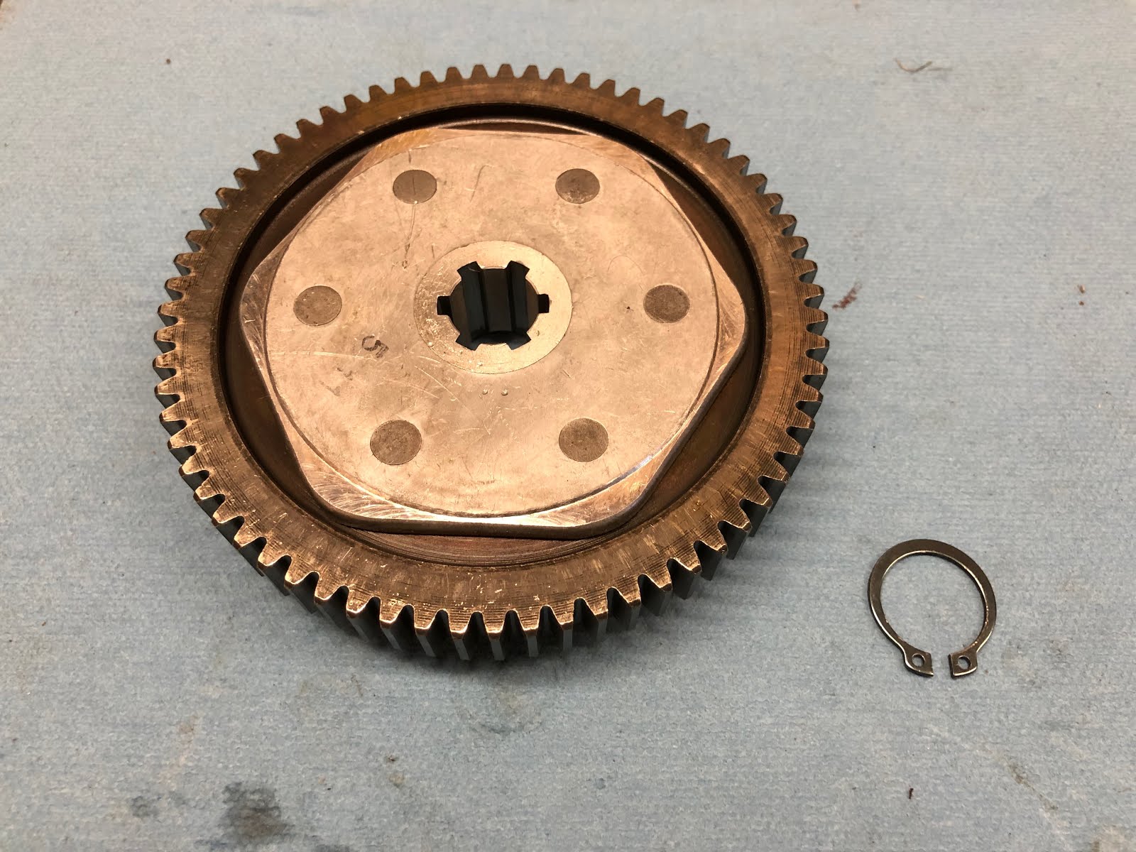
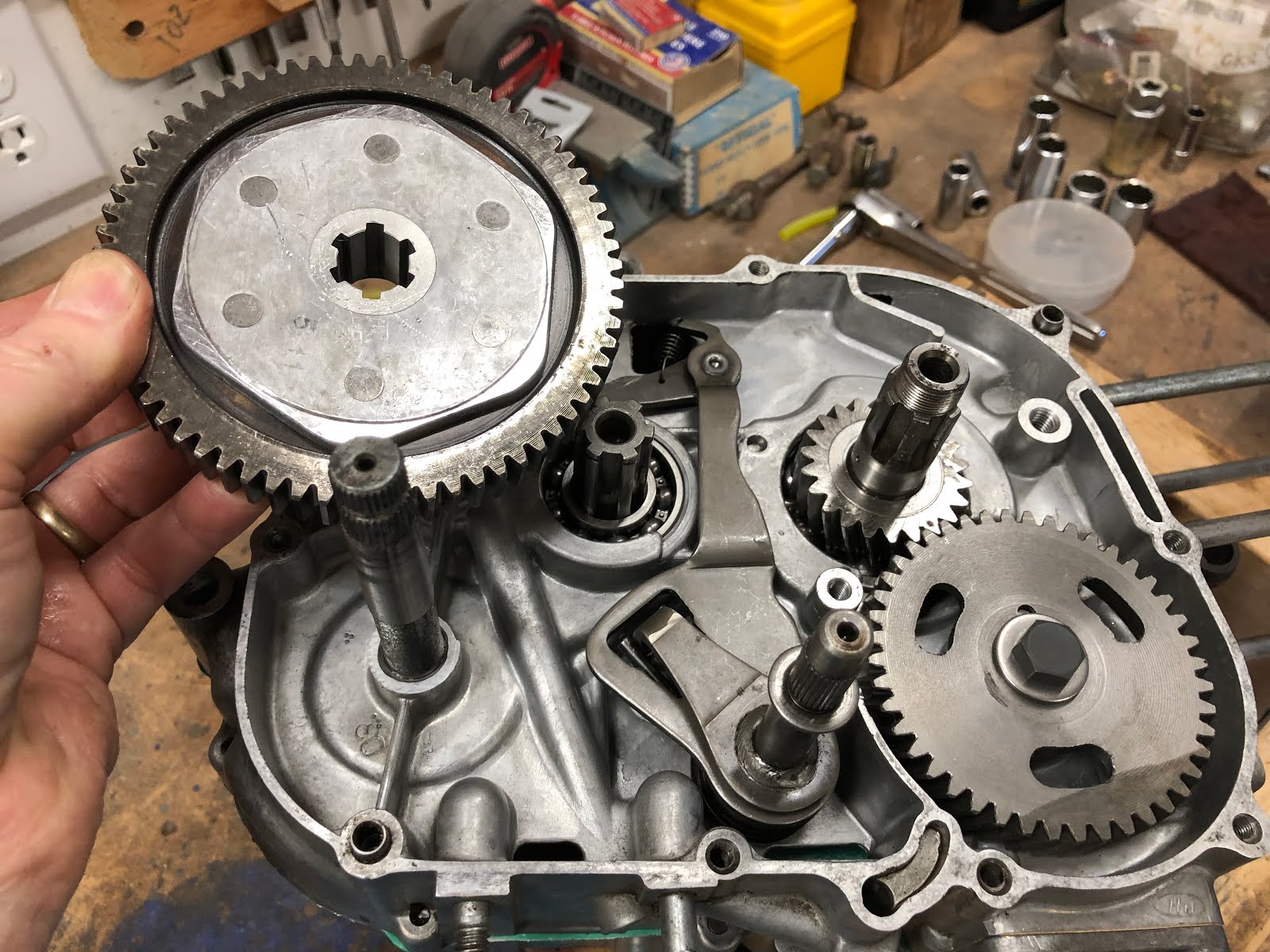
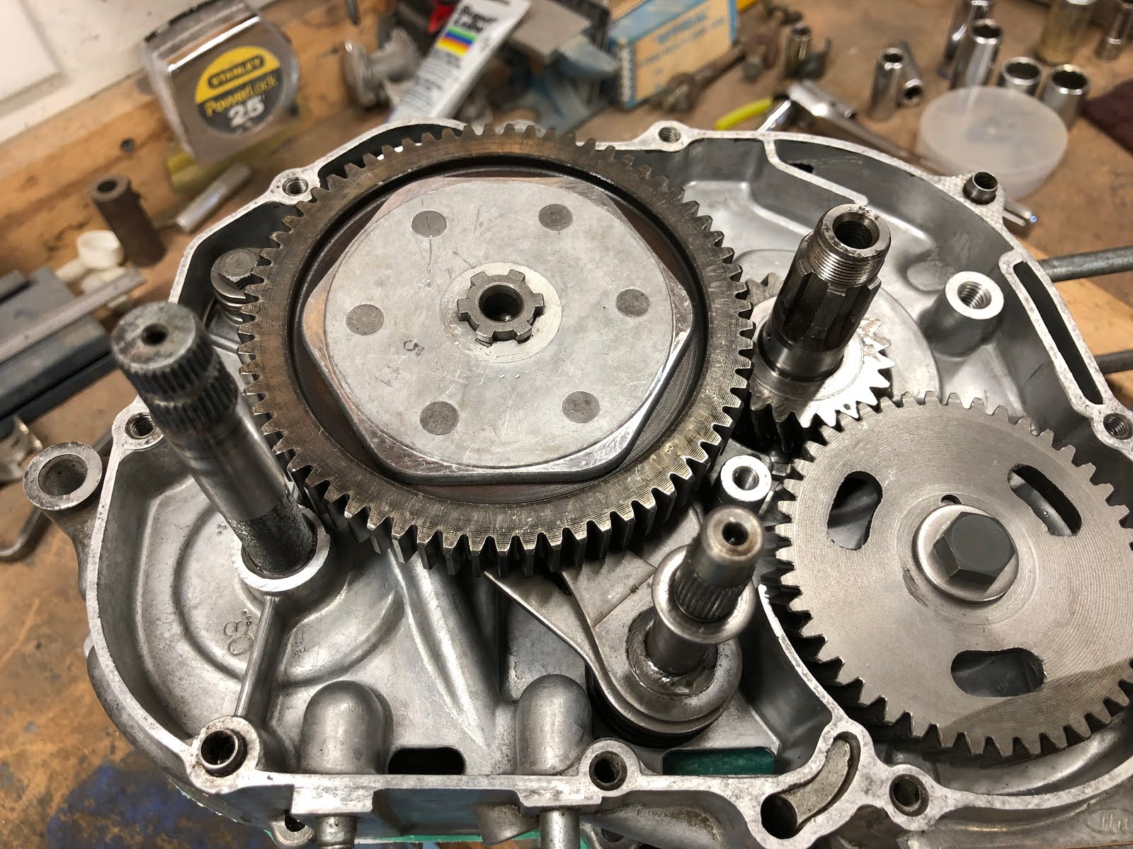
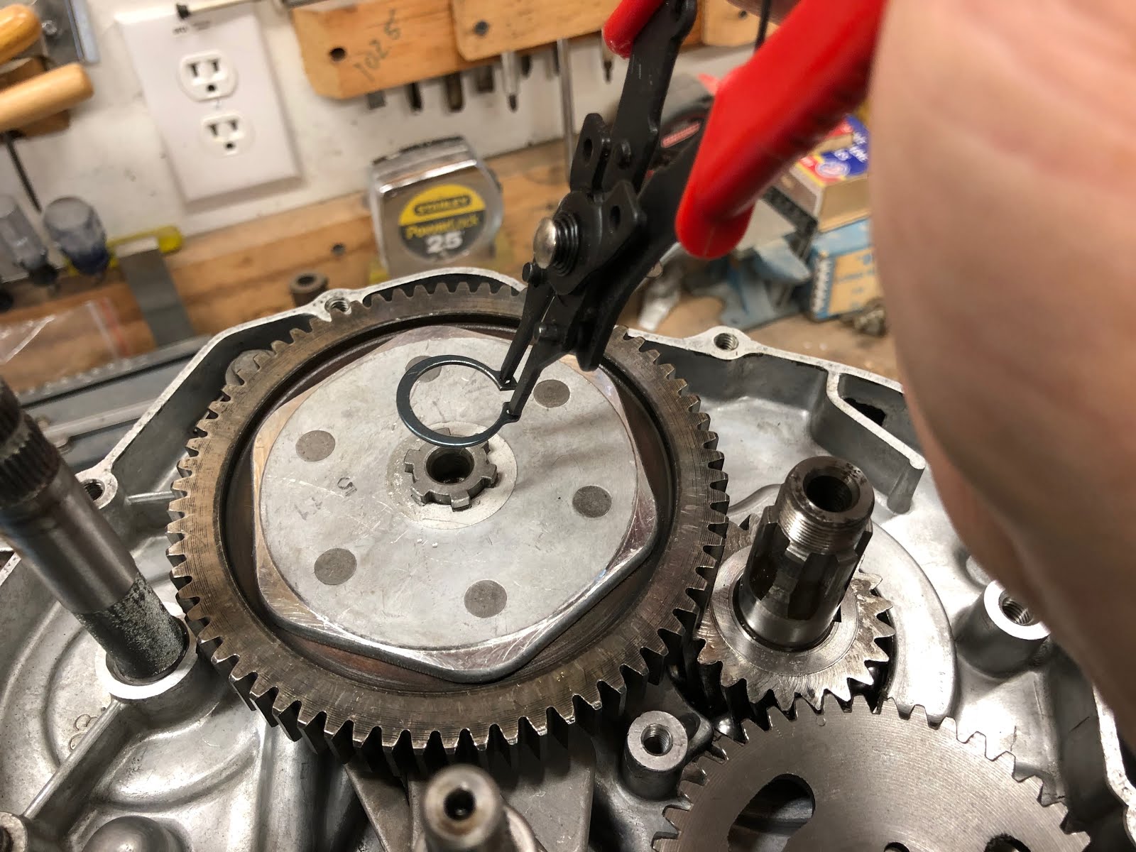
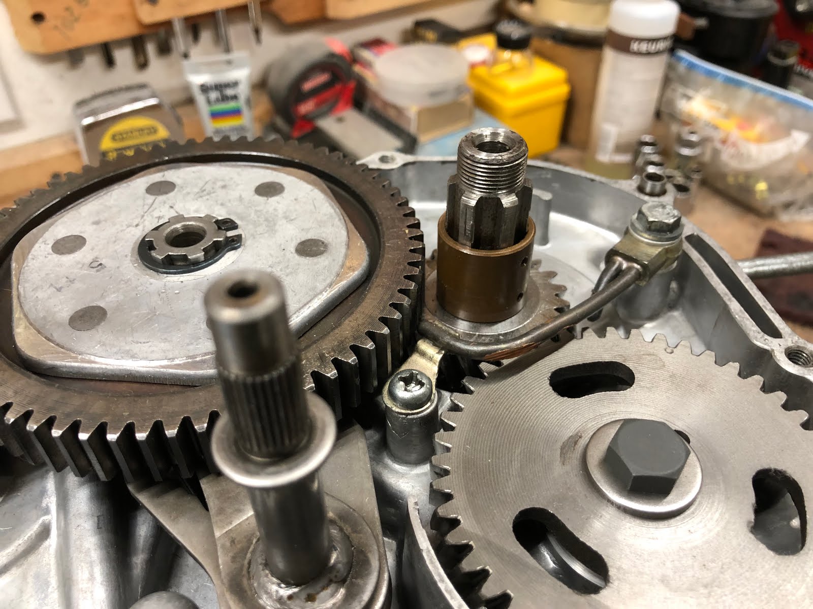
The next step is to install the drive gear shown in the picture below. This step is pretty simple and it just involves placing the drive gear on the shaft and then install the retaining ring that holds it in place.


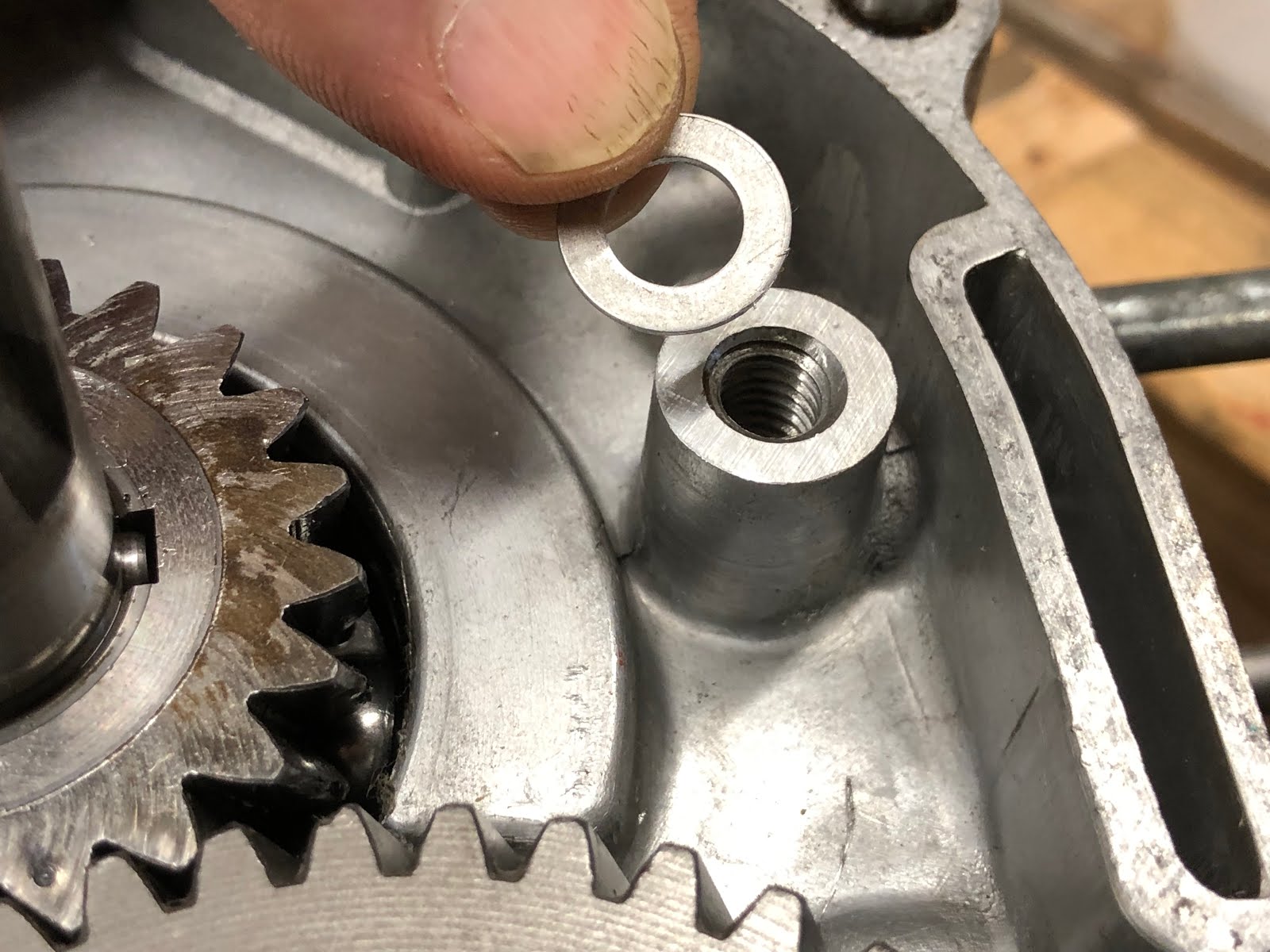
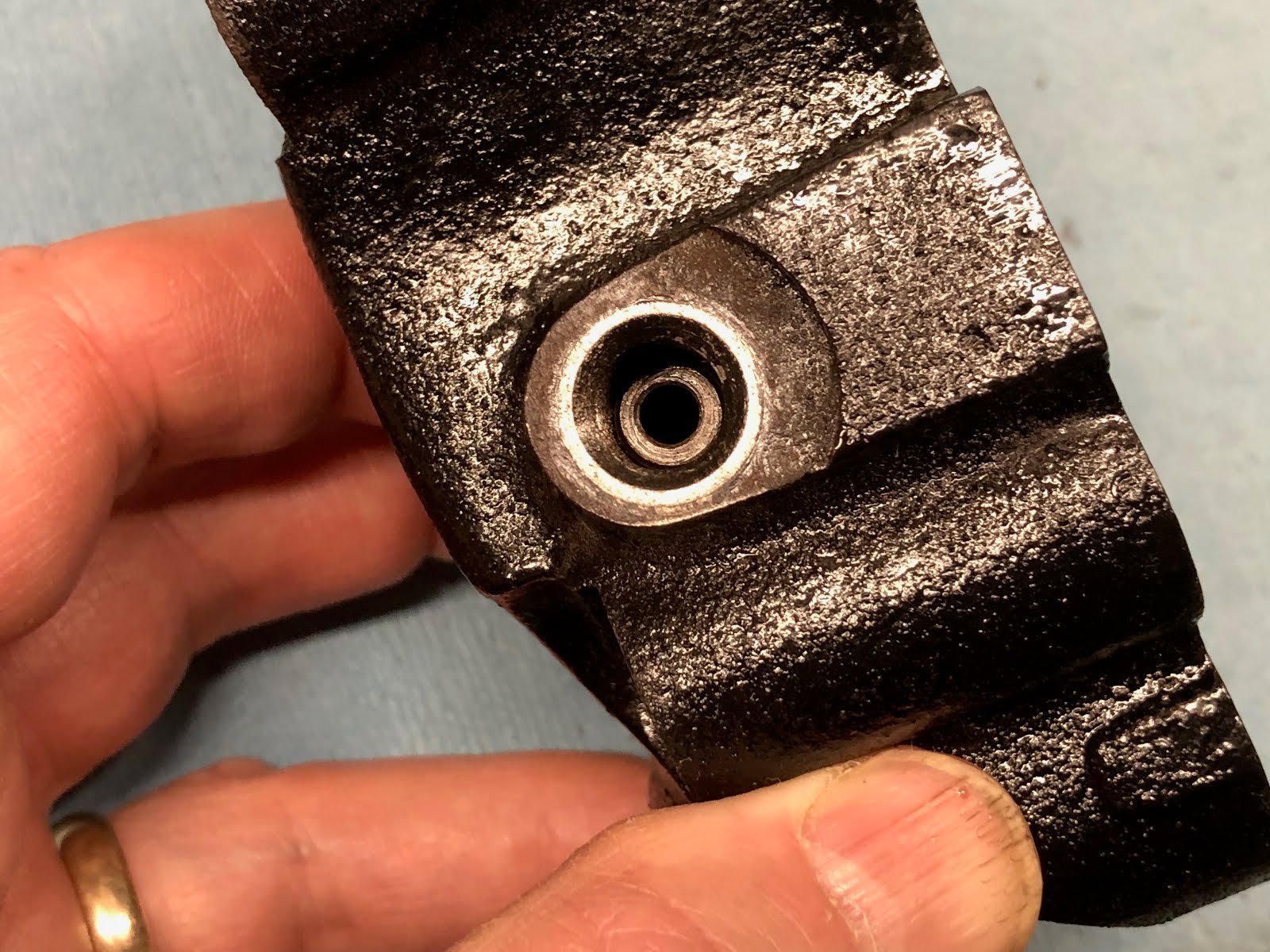
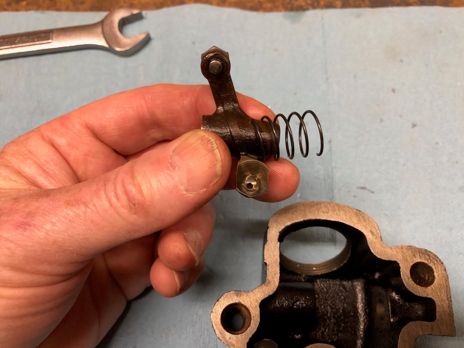
The next step is to install the small assembly that directs oil to the timing and drive gear interfaces.

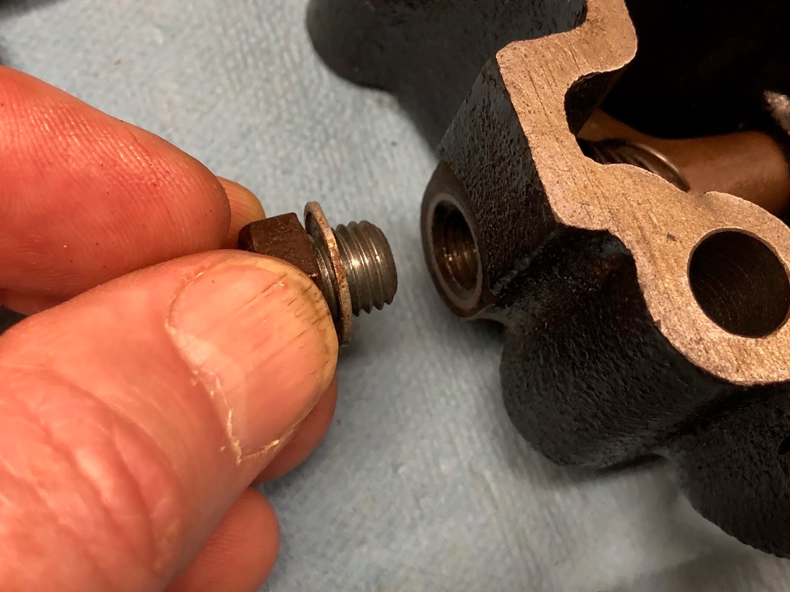
On the one end of the assembly with the banjo fitting there are two aluminum washers that need to be installed. The first goes between the banjo fitting and the housing.
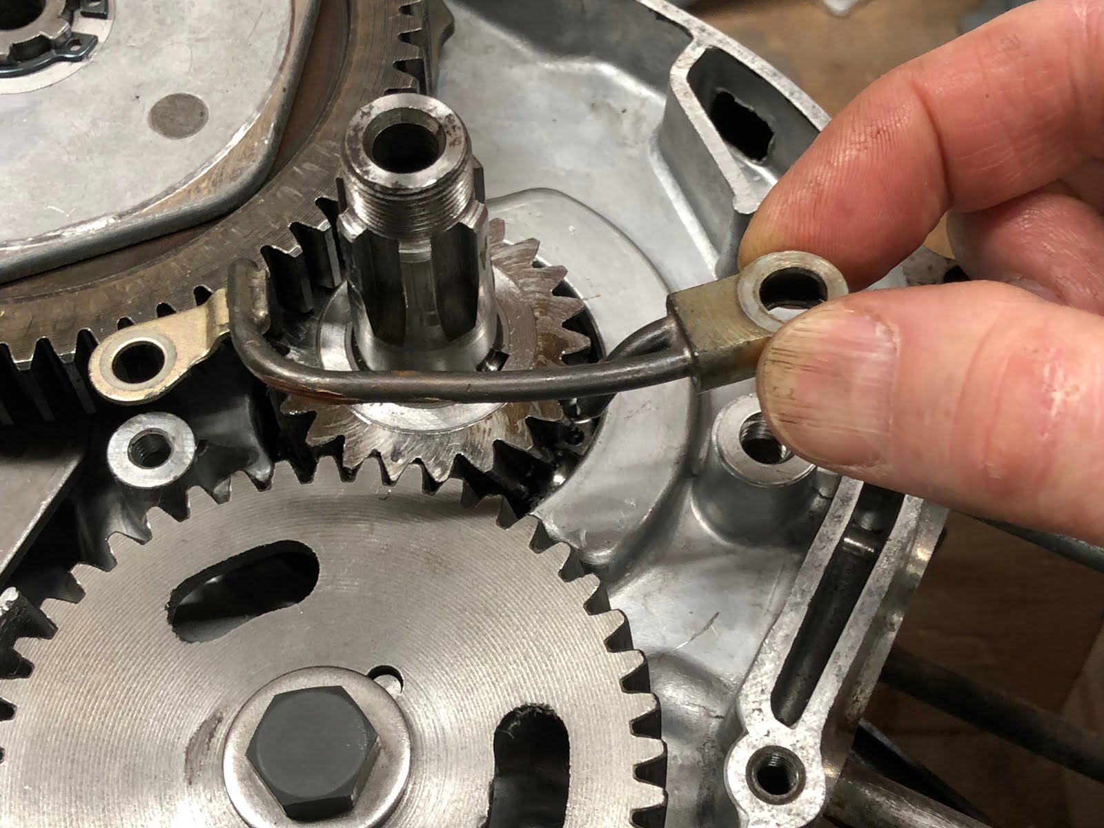
Then position the assembly as shown below.

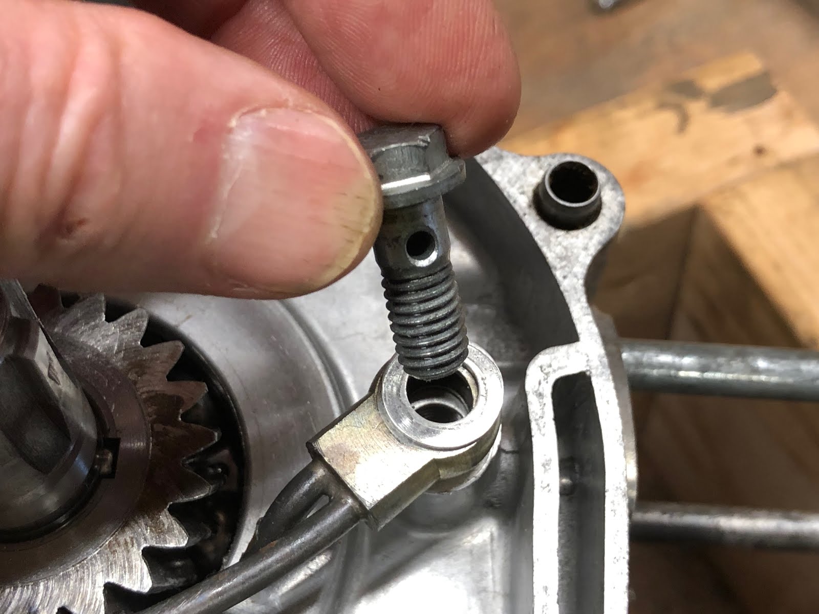
Next place the second aluminum washer on the banjo fitting and install the hollow bolt taking care not to over torque and shear the bolt.

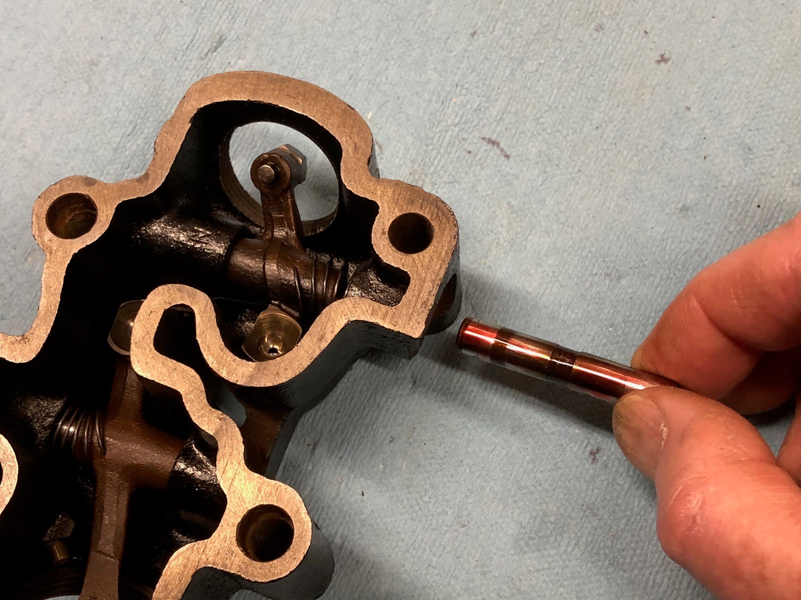
And the last step is to install the screw at the other end of the assembly and then this step is complete.


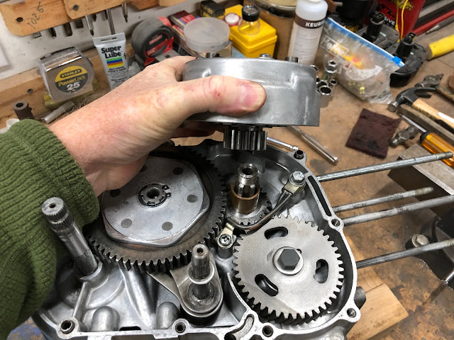
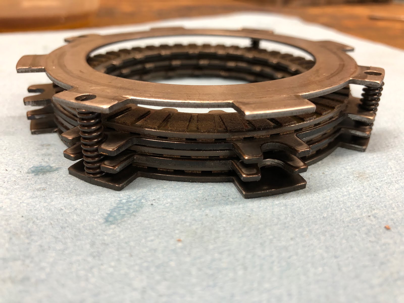
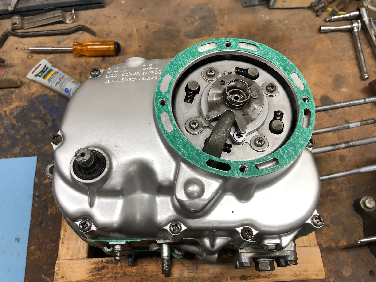
The next step is to install the clutch pack assembly. I am not going tp detail how to assemble a CT200 clutch pack assembly here, but I did do a detailed post on how to build up a CT90 clutch pack assembly which is almost identical. Here is the link to the CT90 clutch pack assembly post. I will include the photo below of how the clutch disks and plates are arranged in a CT200 clutch pack to go along with the information provided in the CT90 clutch pack link to help you make sure that you get your CT200 clutch pack assembled correctly.

Here are the clutch pack and associated components from our CT200 that we will install next.

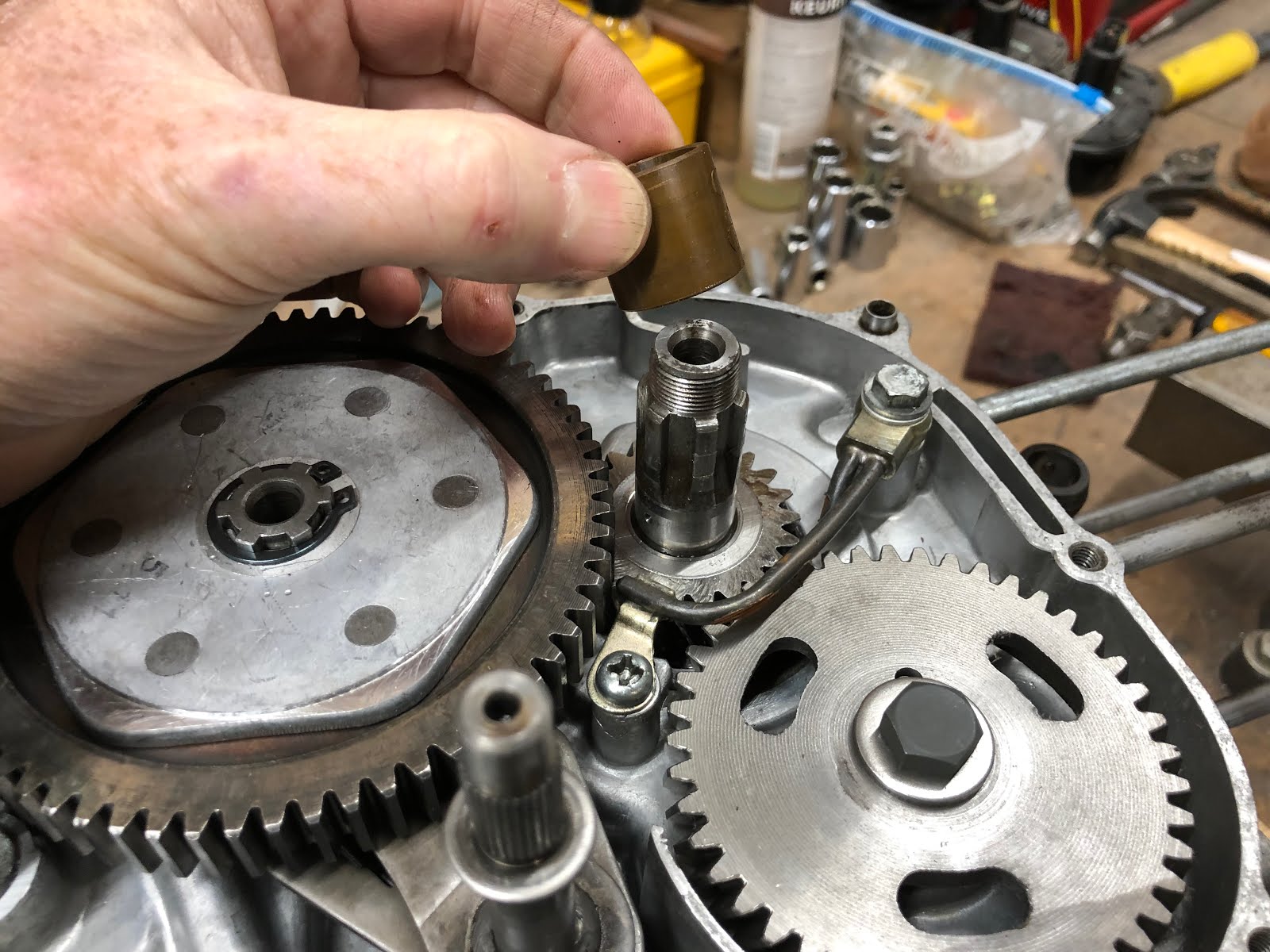
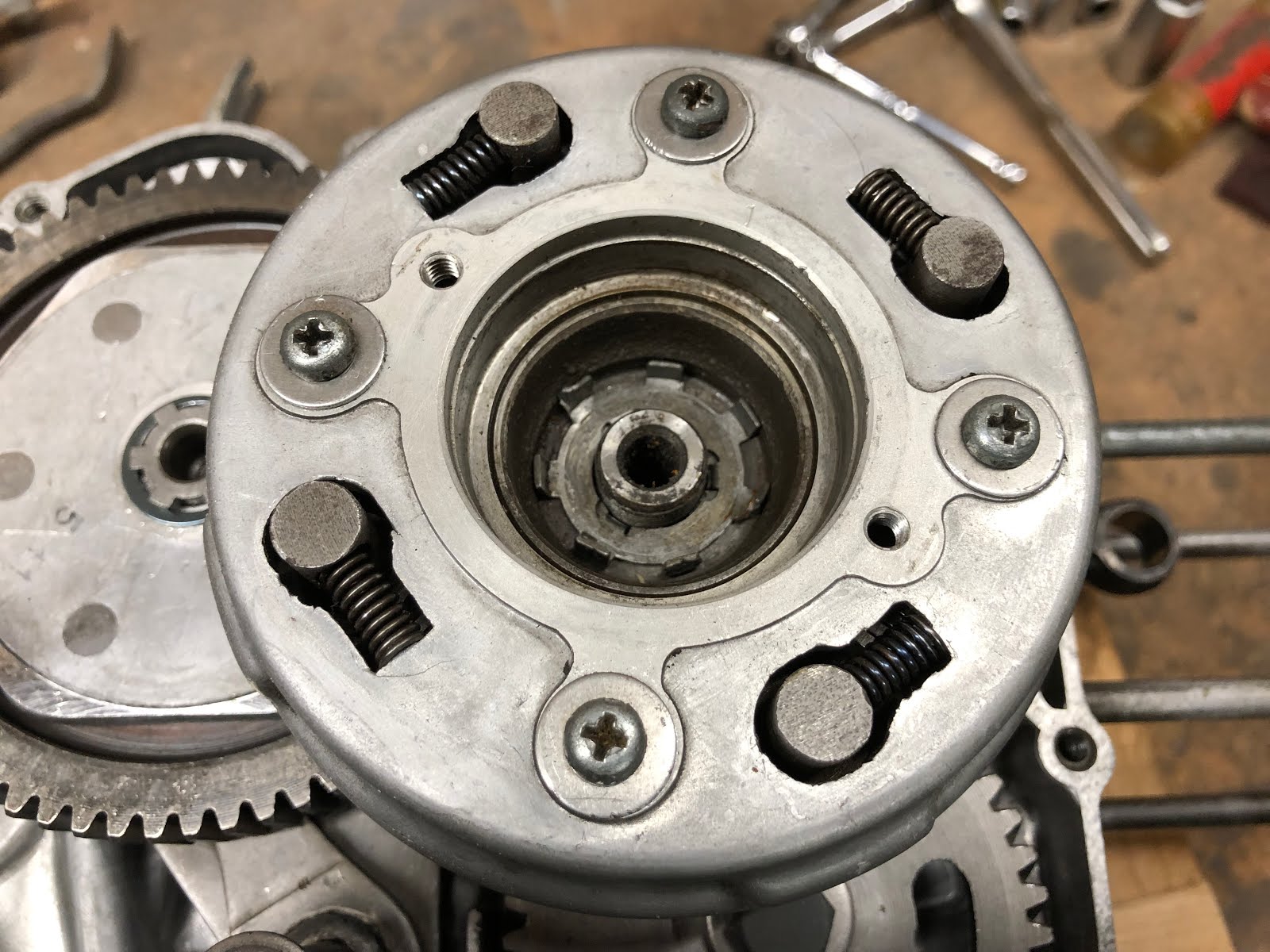
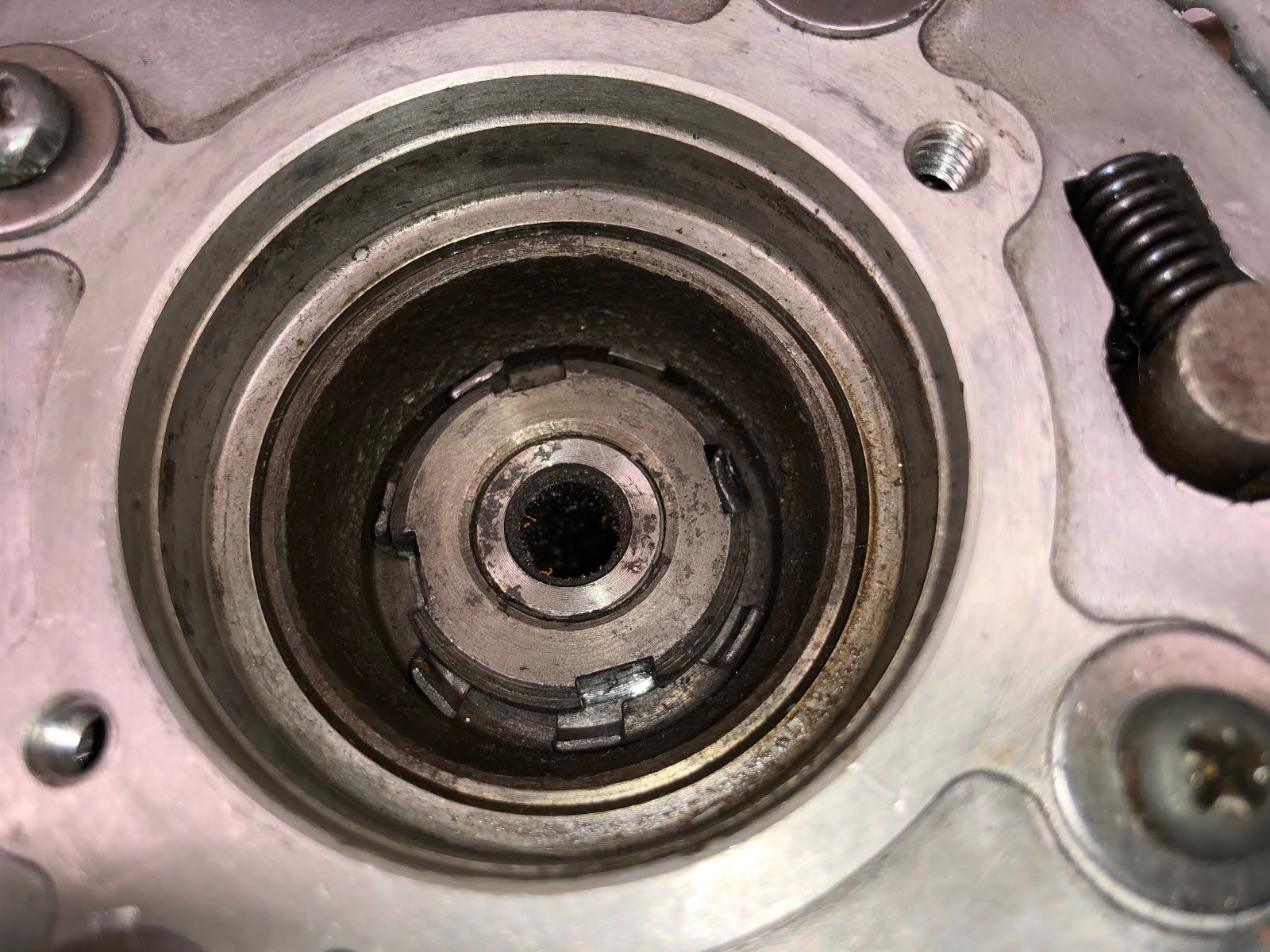
The first step is to install the bushing over the shaft of the crank.


The next step is to install the clutch pack assembly onto the crank shaft and get it engaged with the drive gear.
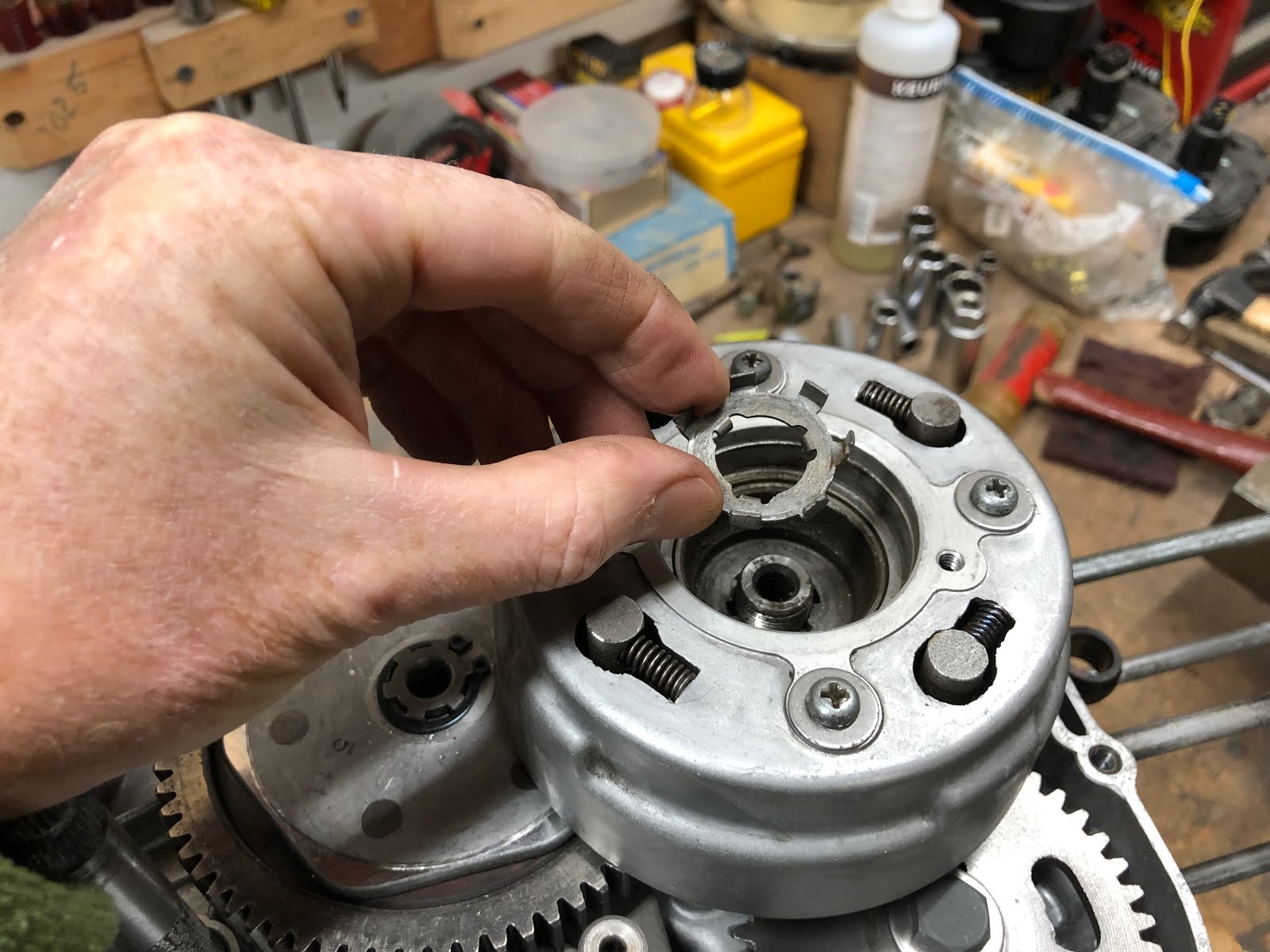
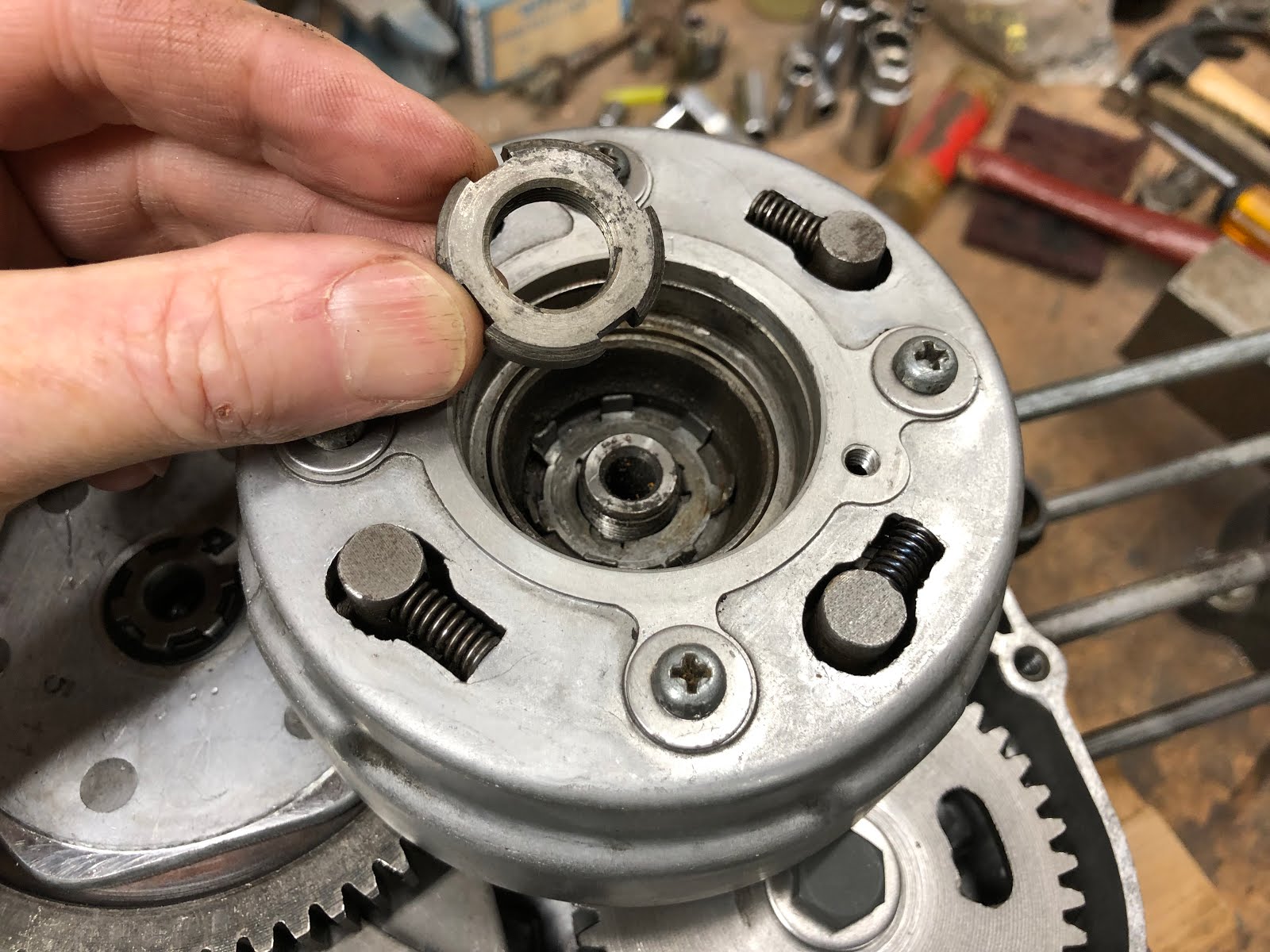
The next step is to drop in the lock washer and make sure the inner tabs are engaged with the slots/splines of the clutch pack assembly.

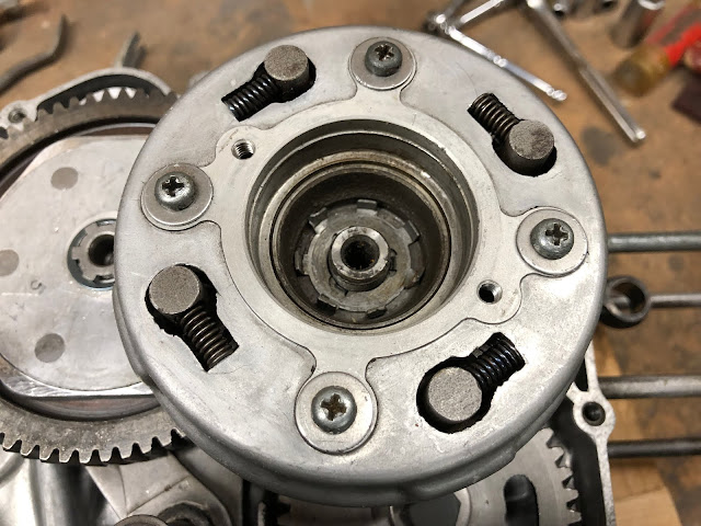
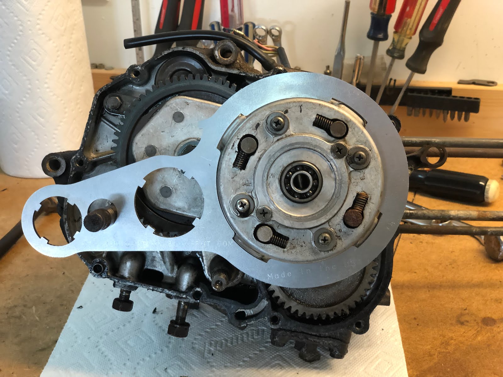
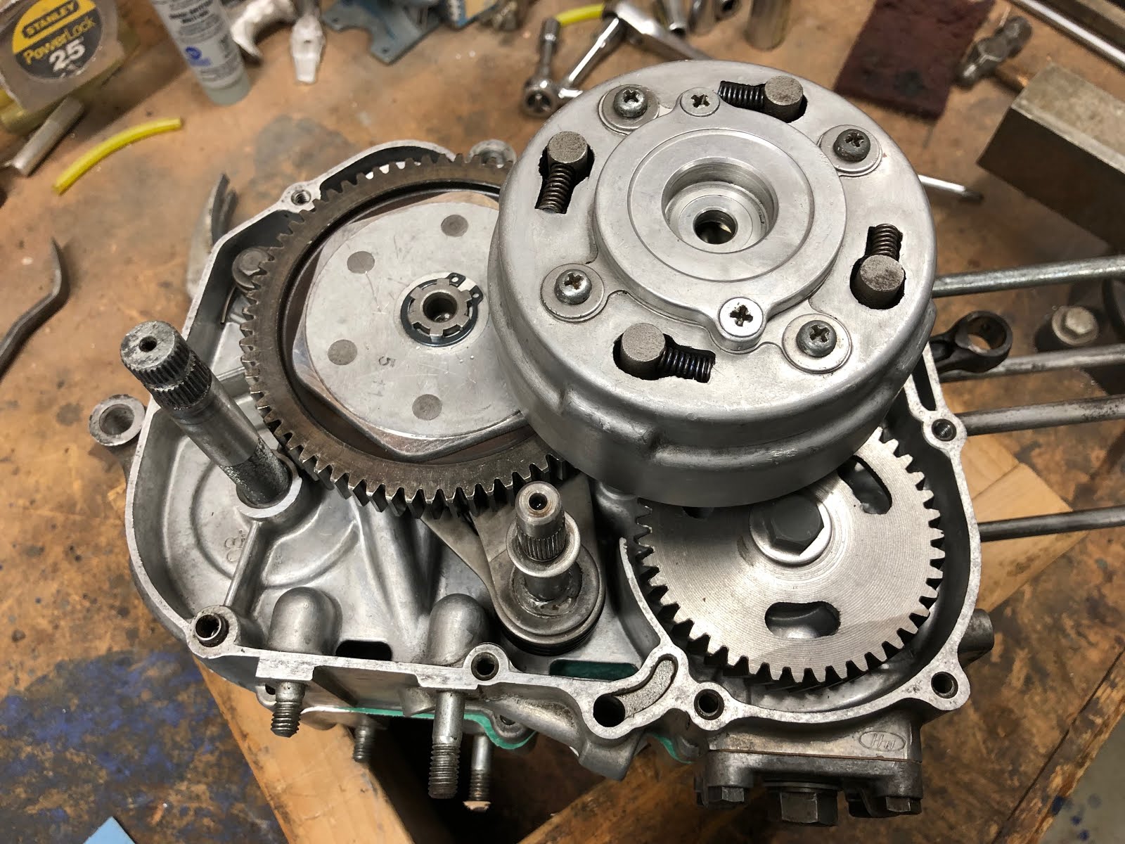
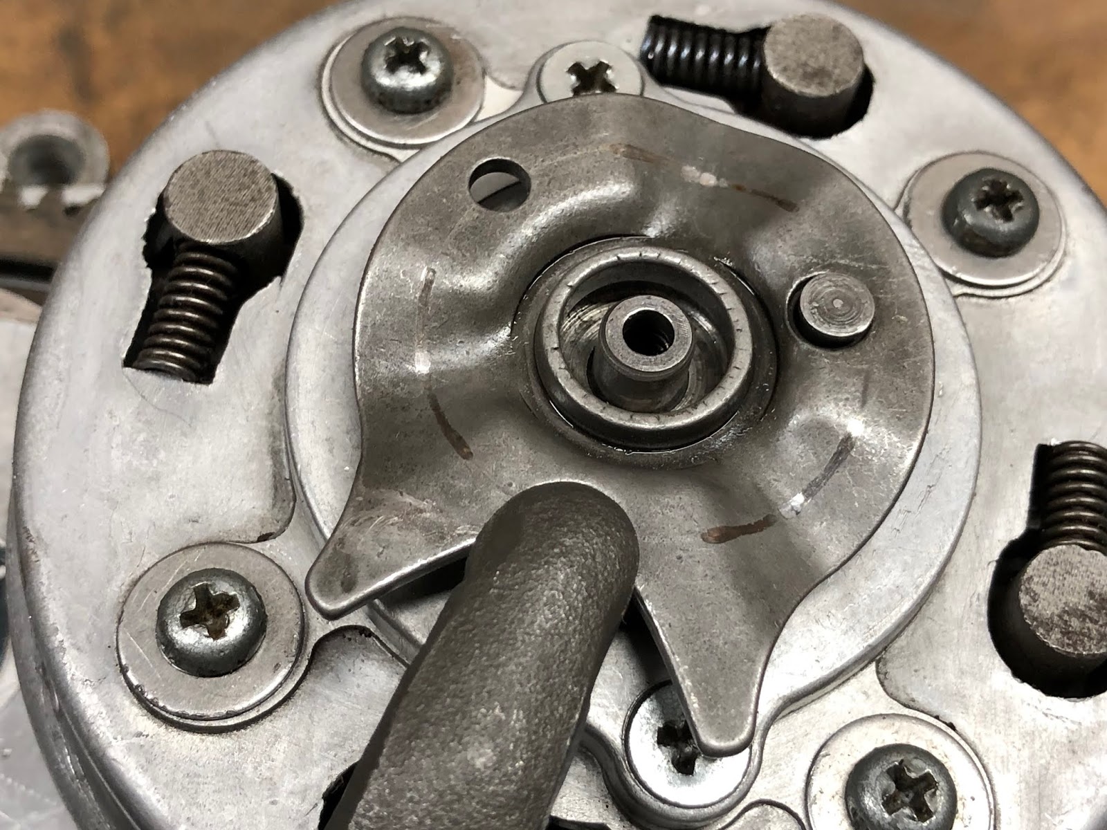
Next install the nut that will retain the clutch pack and use a tool to hold the clutch pack (not shown) and a special tool to torque down the nut with a torque wrench.

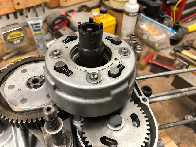
I also now sell the clutch holding tool in the picture below that I designed and that can also be used to loosen the headset nuts on most Honda CT90's and CT200's. Here is a link to the post I did that includes a link to where I sell the tool on eBay.

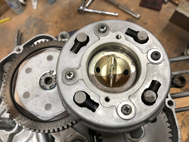
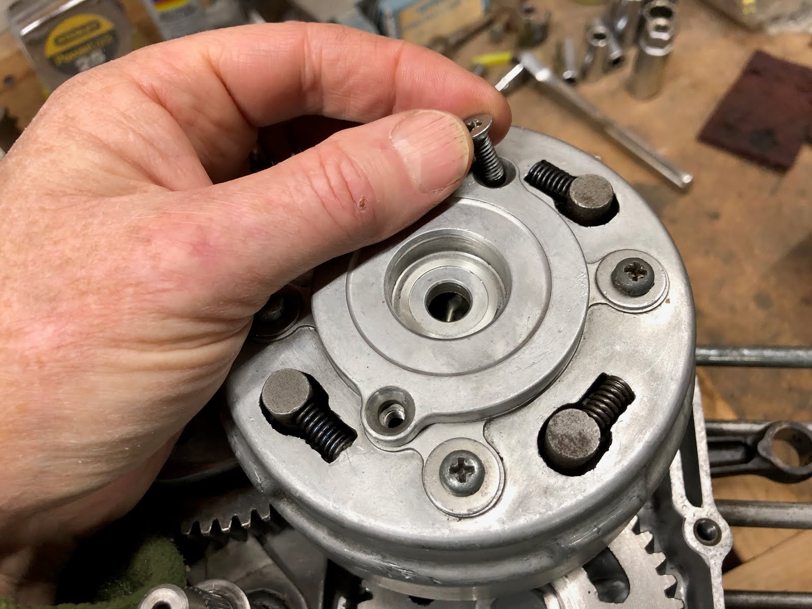
With the nut torqued down fold up one of the tabs on the lock washer into the nearest slots on the nut like what is shown in about the 2:30 position in the picture below..

Next install the stamped sheet metal divider into the center of the clutch pack opening.

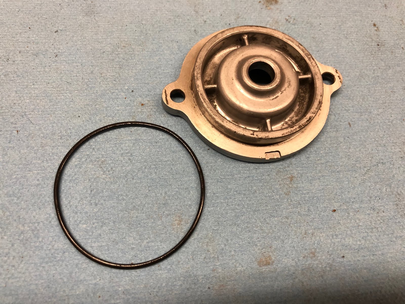
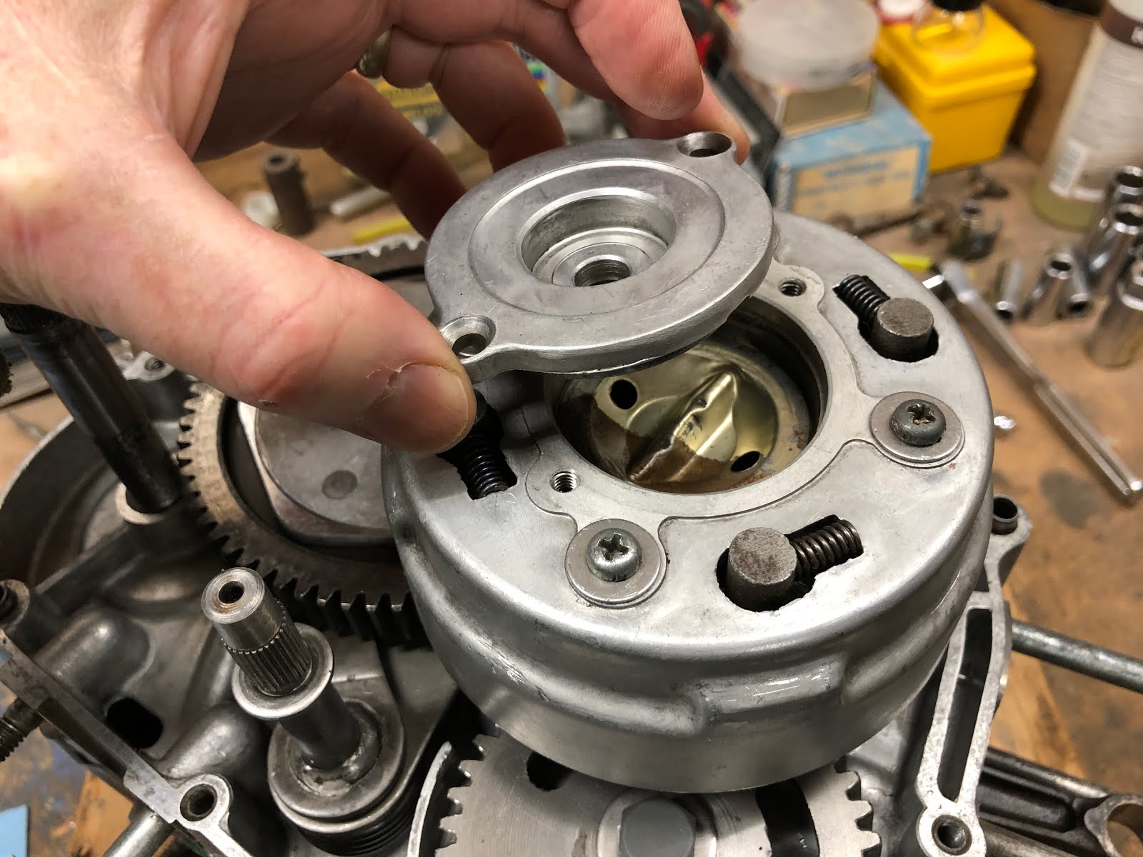
The next step is to install the cover on the clutch pack assembly. The cover has an o-ring that has an ID of 1.90 inches and a .060 diameter cross section which is first installed in a groove on the cover.

Next install the cover using the two countersunk head screws.


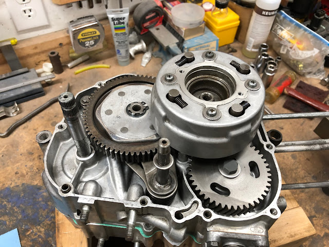
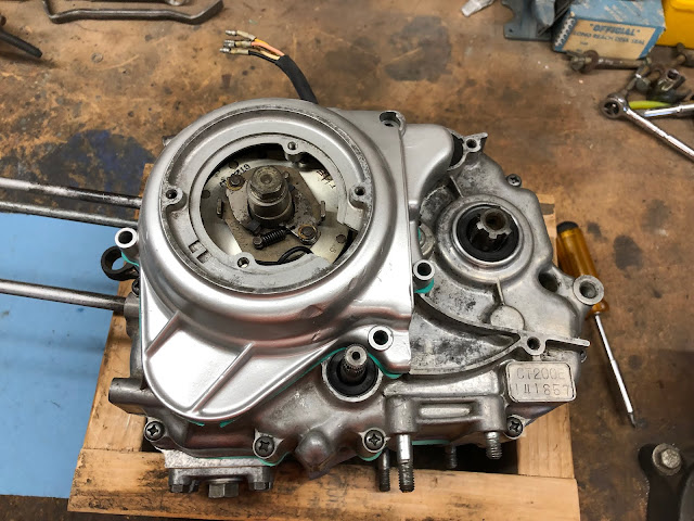
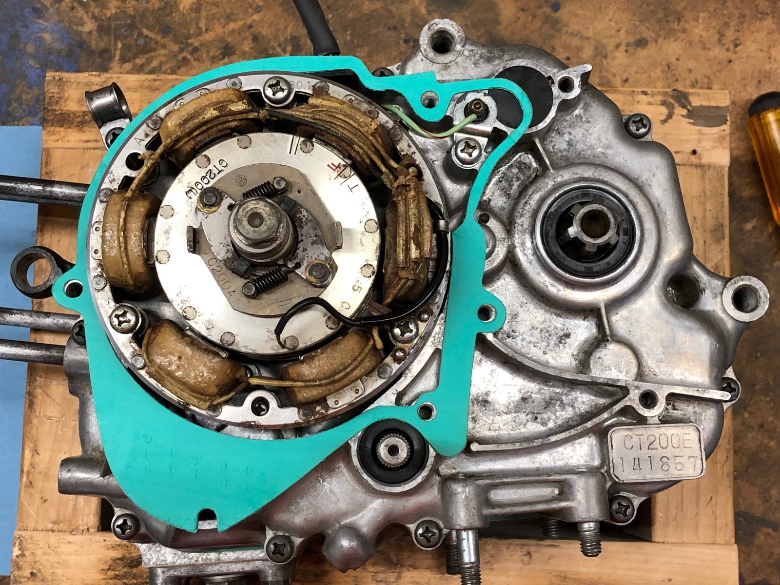
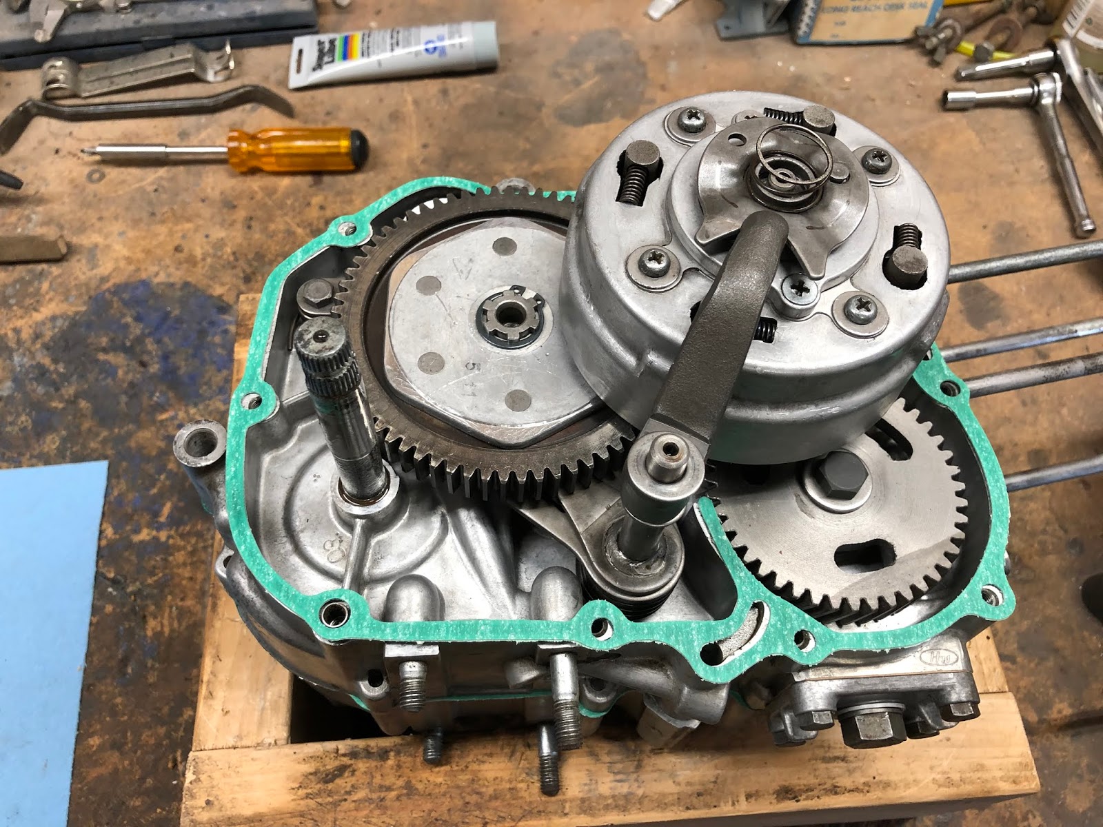
With the clutch pack installed which now gives us a way of holding the crank we'll flip the engine over and install the remaining components on the left side of the engine.

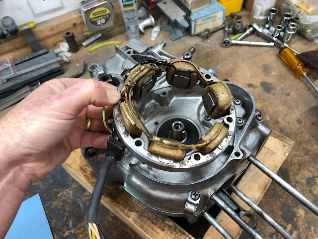
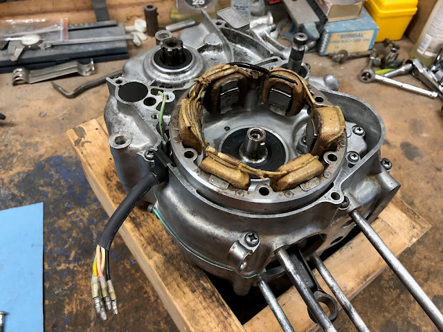
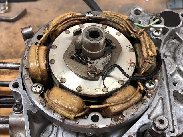
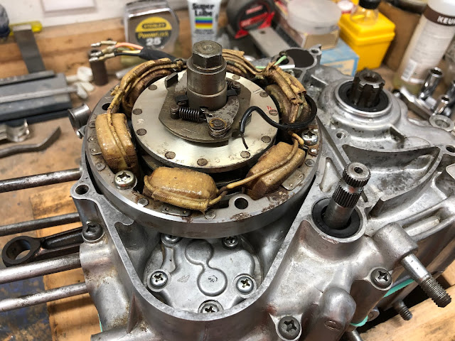
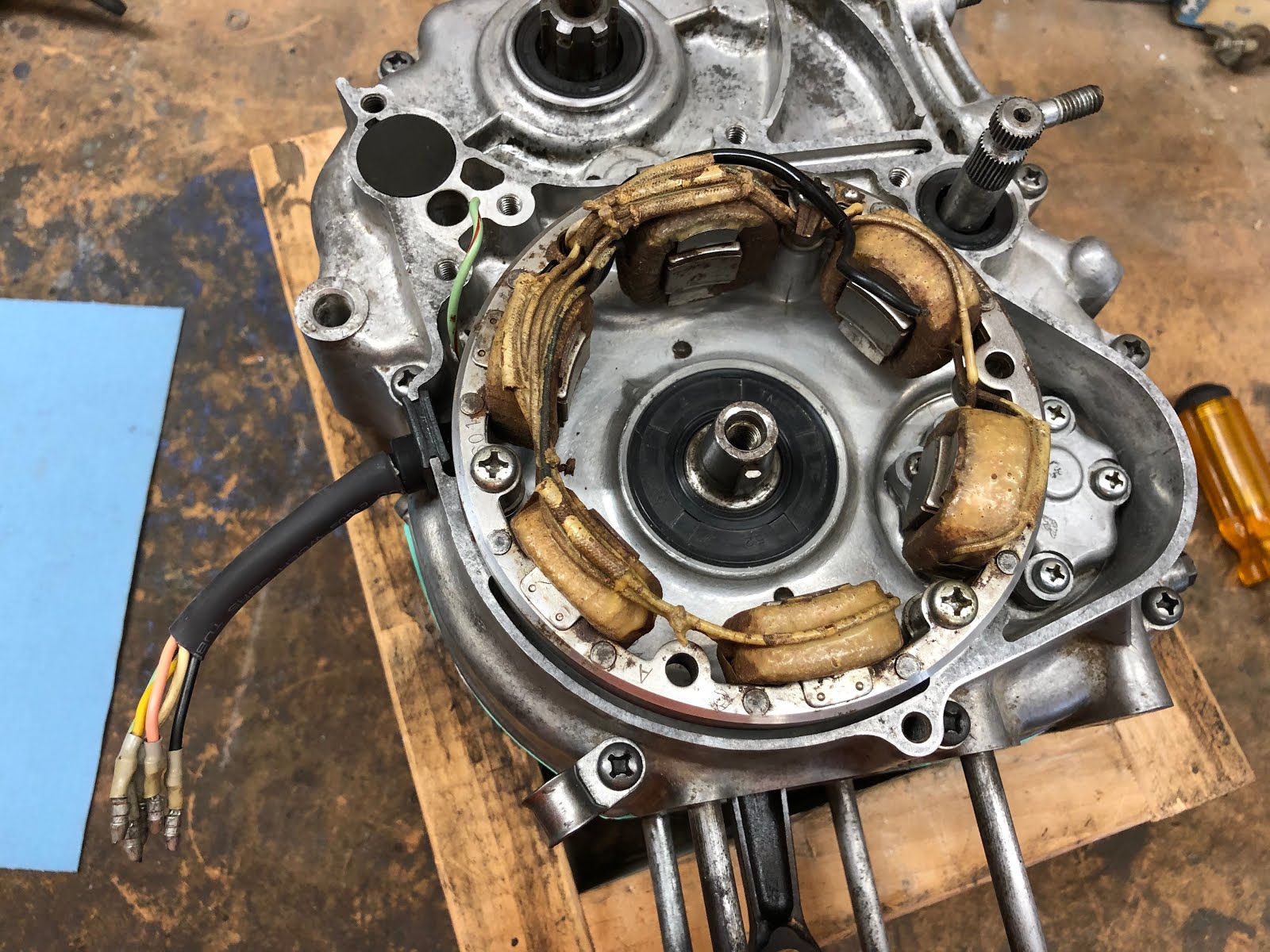
The first thing we will install is the alternator stator assembly.
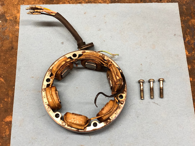
The alternator stator is installed by lining up the wire bundle rubber grommet with the opening in the housing and then setting the stator in place lining up the three appropriate holes in the stator with the three threaded holes in the housing and then install and torque down the mounting screws.

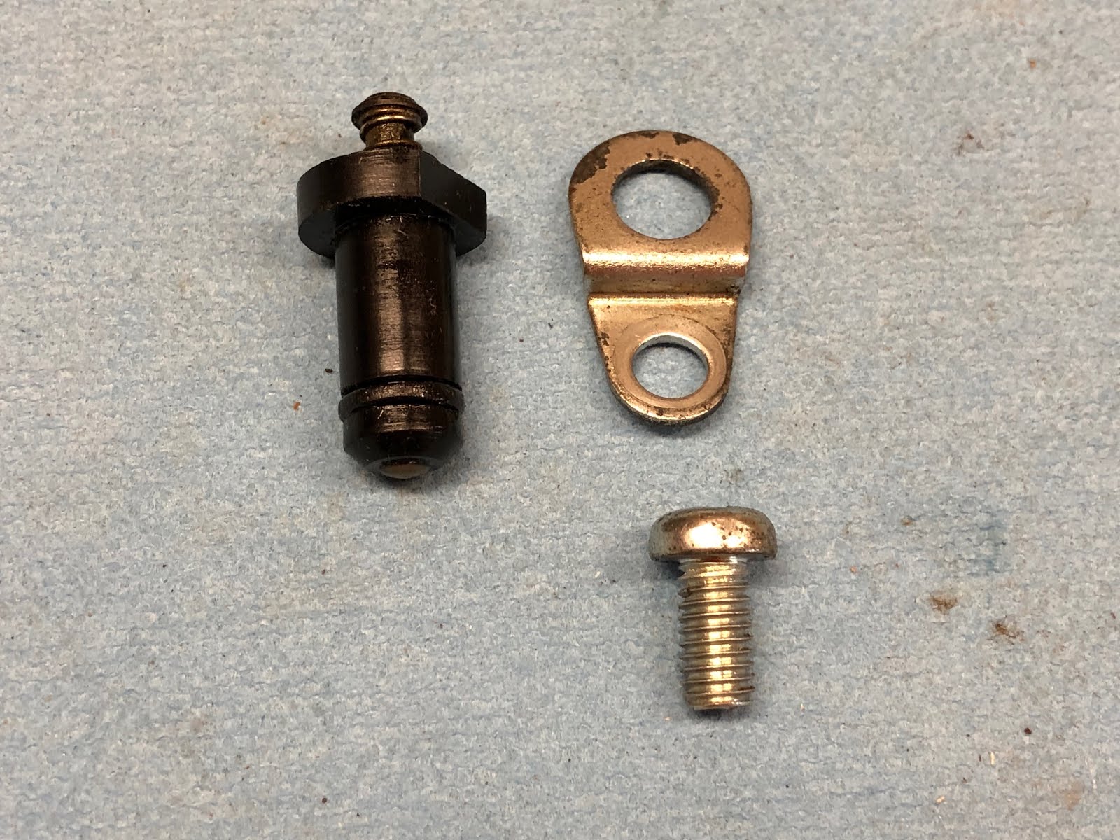
The next step is to install the components that make up the other half of the neutral switch that are shown in the picture below. The neutral switch is really just the copper tab on the shift drum and this neutral conductor encased in a black plastic. When the copper tab on the shift drum comes in contact with the nub at the end of this component it completes the ground path for the neutral light.
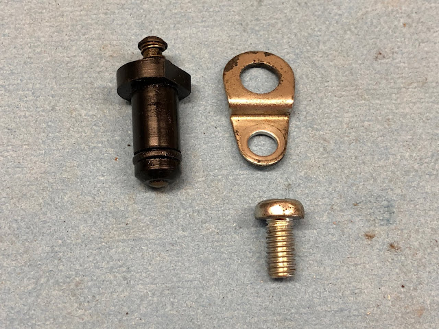
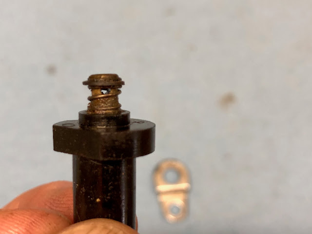
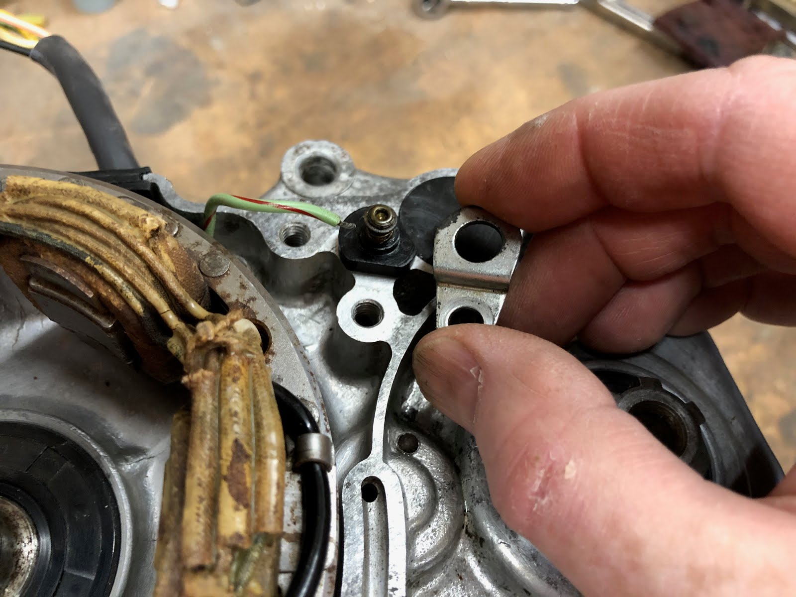
The first step is to install the conductor in its hole in the housing making sure the o-ring is installed on the end of the conductor. The straight edge on the rim of the conductor should face the thread hole for the screw that will lock down the conductor retainer.

Then install the retainer and screw.


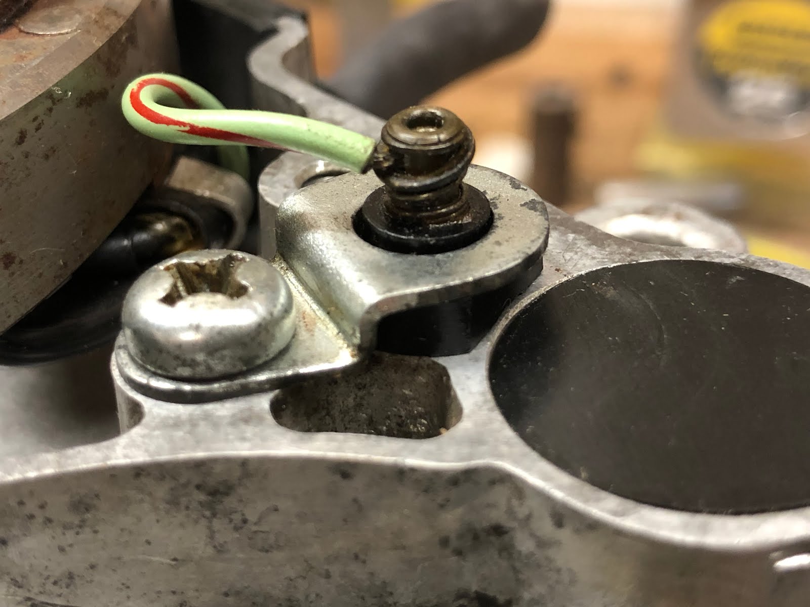
To attach the wire from the neutral light the conductor has a spring loaded washer at the top end which is depressed and then the end of the wire is inserted in the through hole at the top end of the conductor. When you release the washer it will hold the wire in place.

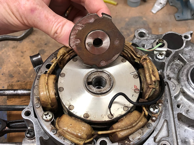
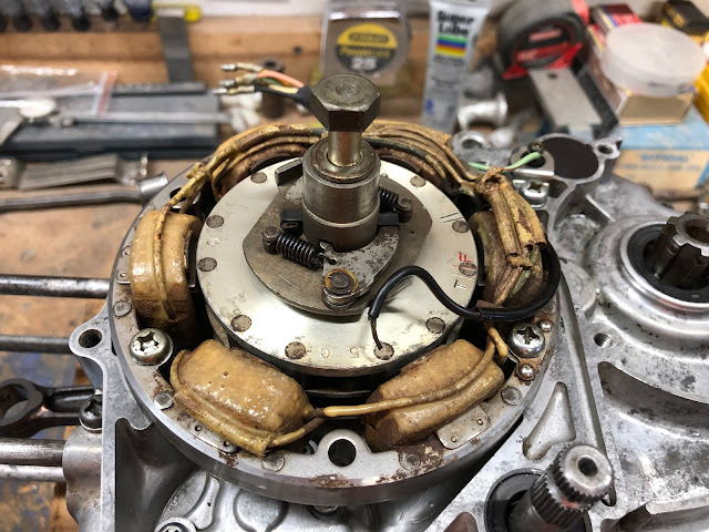
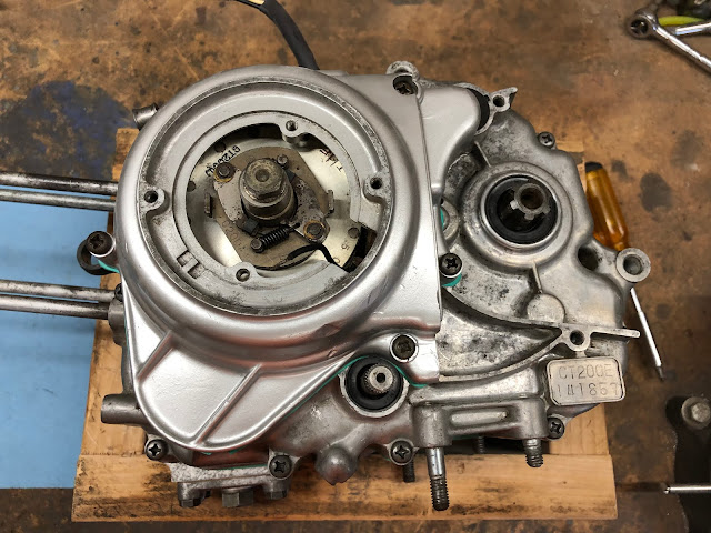
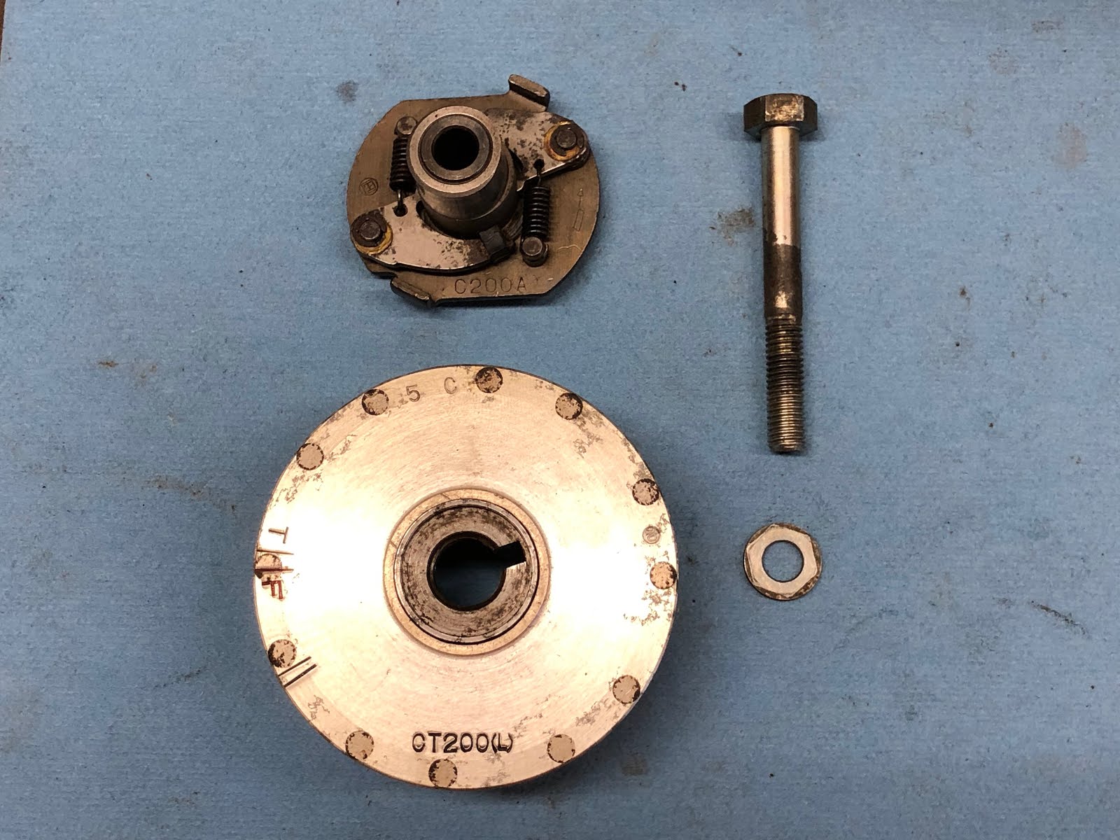
The next step is to install the alternator rotor and the spark advancer. I have a post at the link here on how to assemble a CT200 spark advancer.

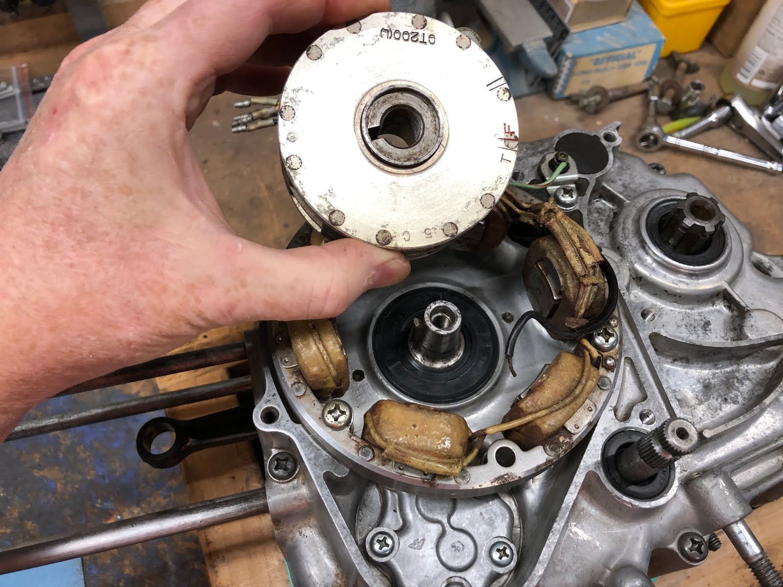
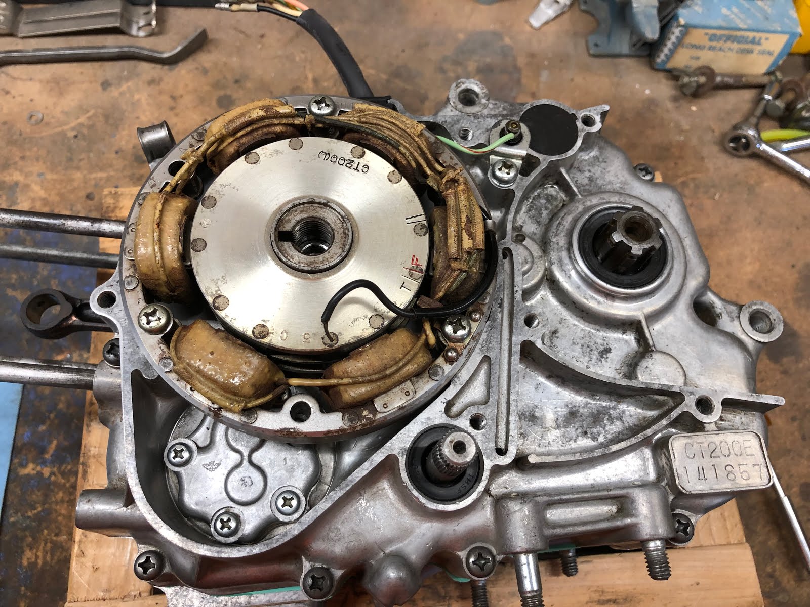
The first step is to install the alternator rotor by lining up the keyway slot in the rotor with the key on the crank shaft and then install the rotor.


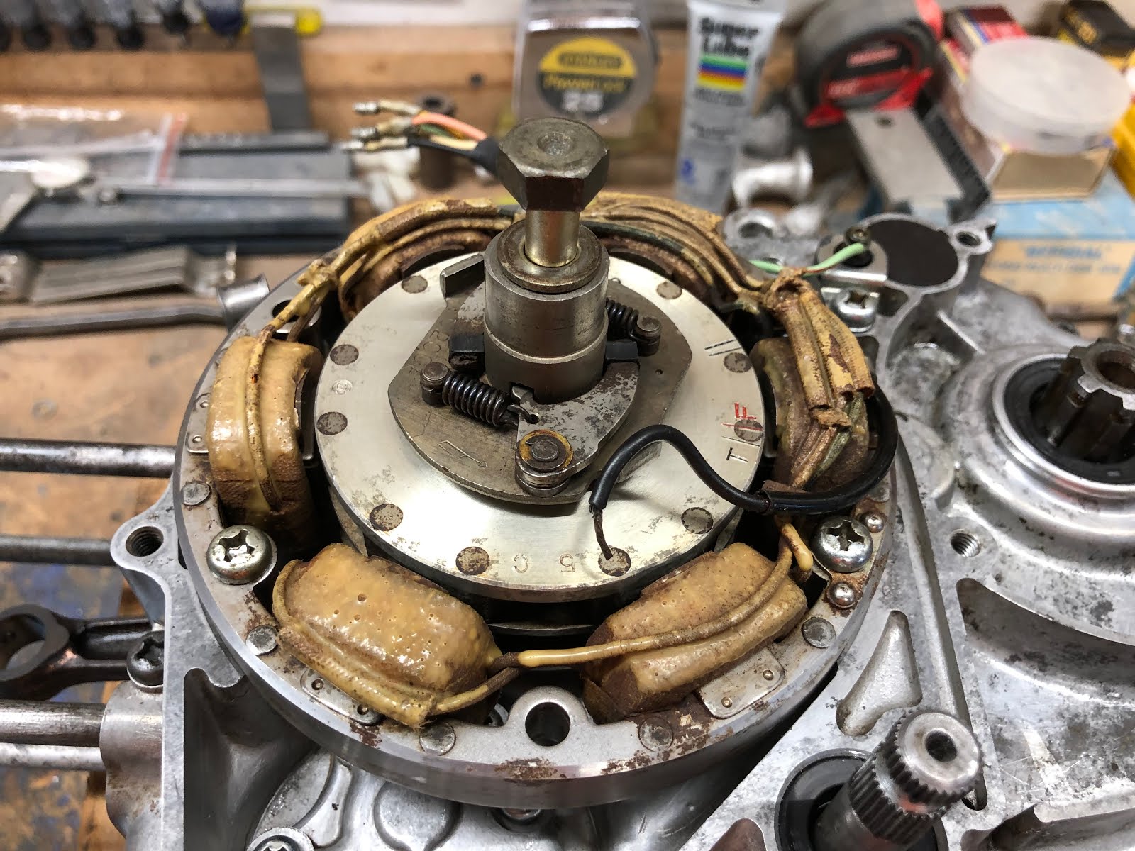
Next line up the pin in the base of the spark advancer with the keyway on the top of the alternator rotor and set in place.
Next install the washer and bolt that retains the spark advancer and alternator rotor and torque to the appropriate value. To torque the bolt you will most likely need to remove the engine from the wood block and use a suitable retaining tool on the clutch pack assembly. Also, if you are so inclined you may want to add a little blue Loctite to the threads of this bolt before installation.

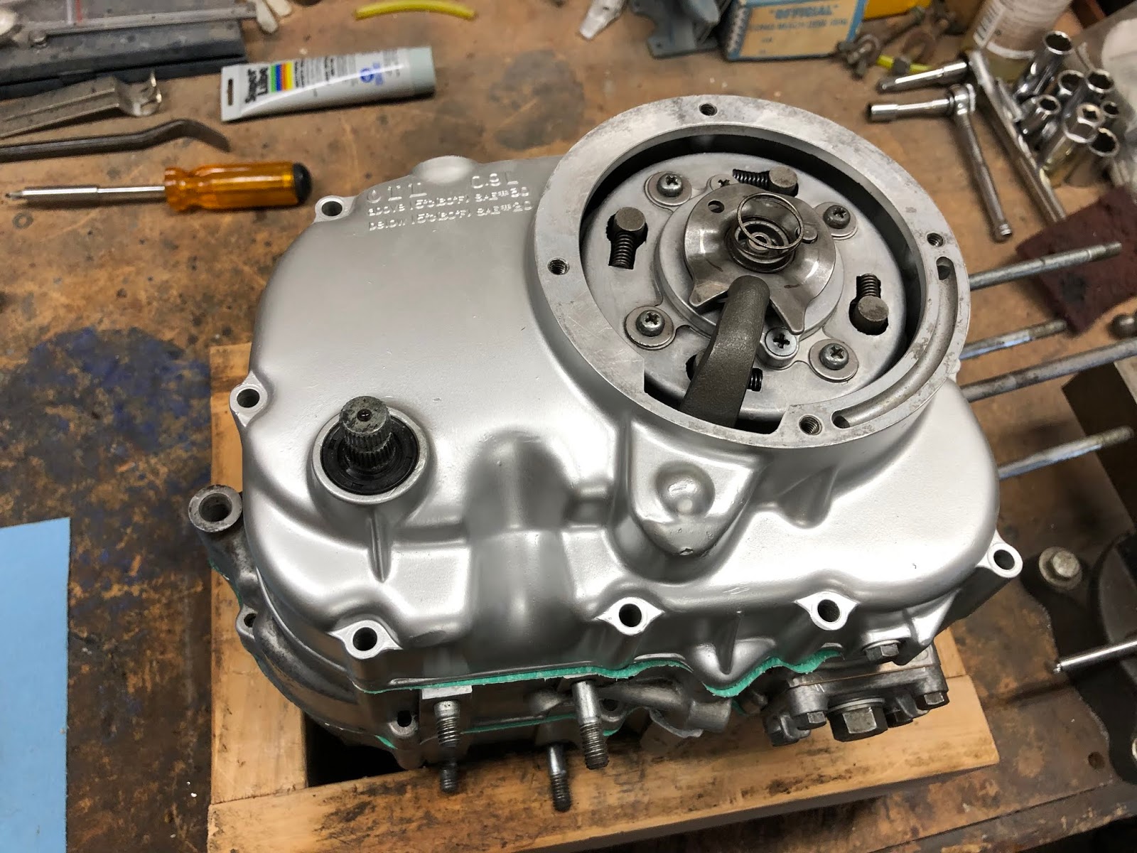
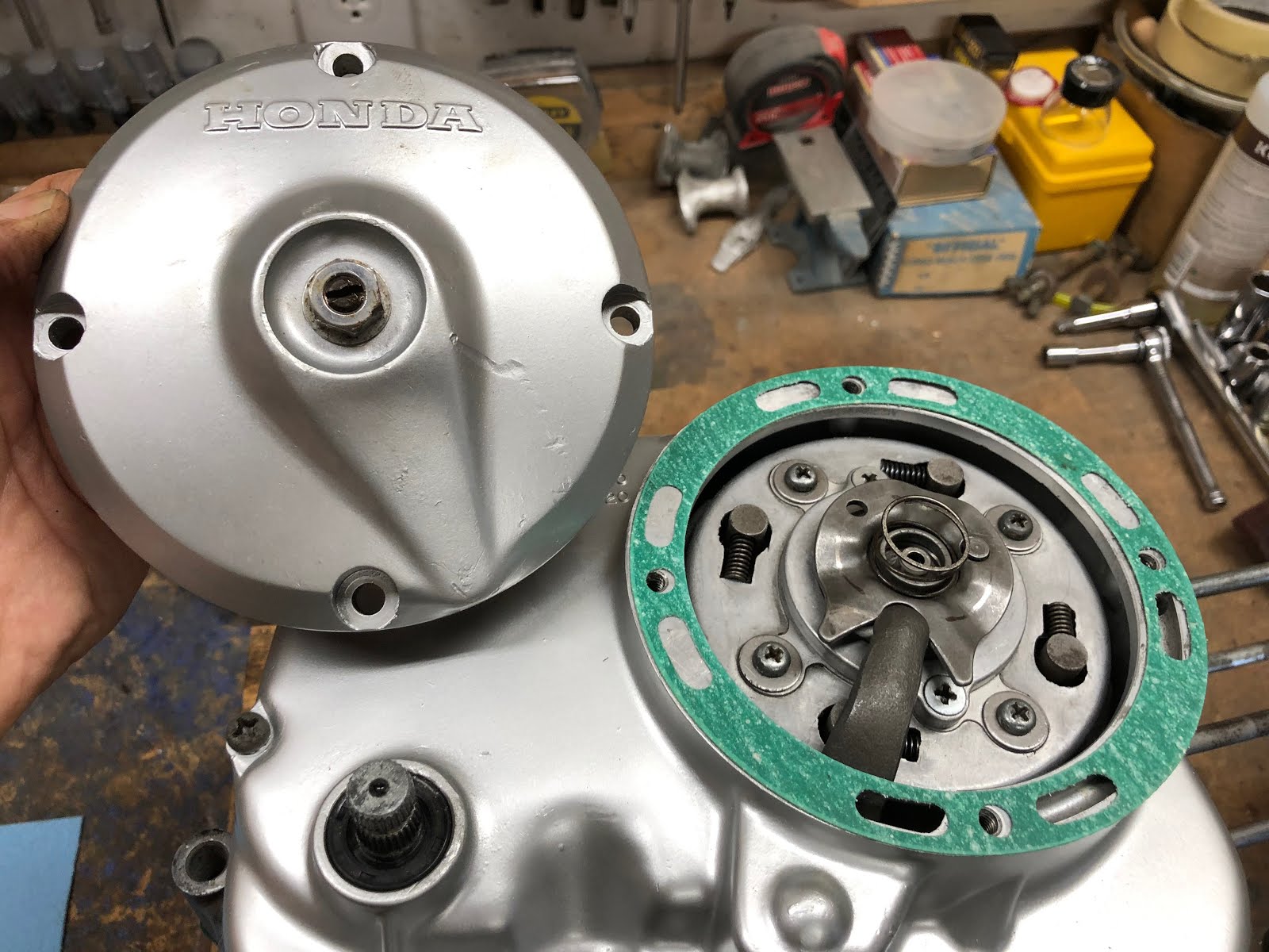
The next step is to install the cover for this portion of the engine.
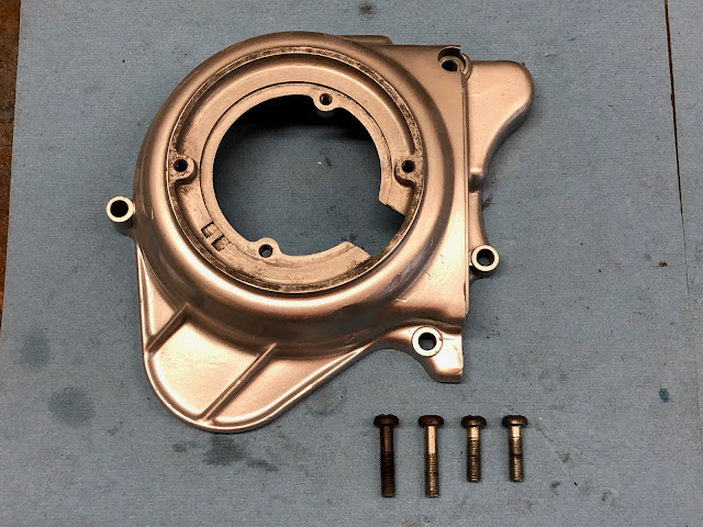
First install the gasket which is then followed by the cover and screws.

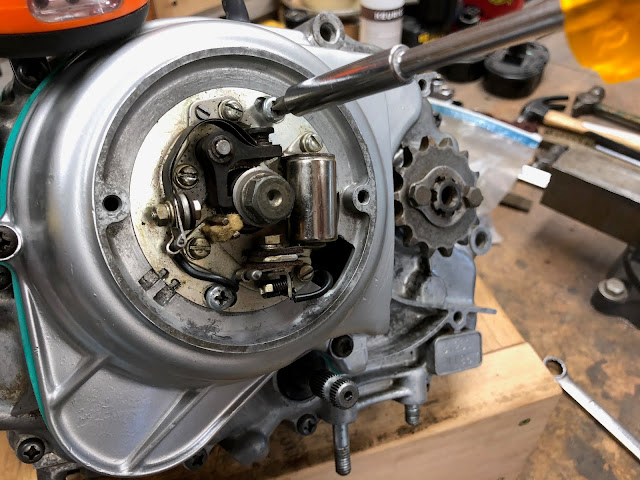
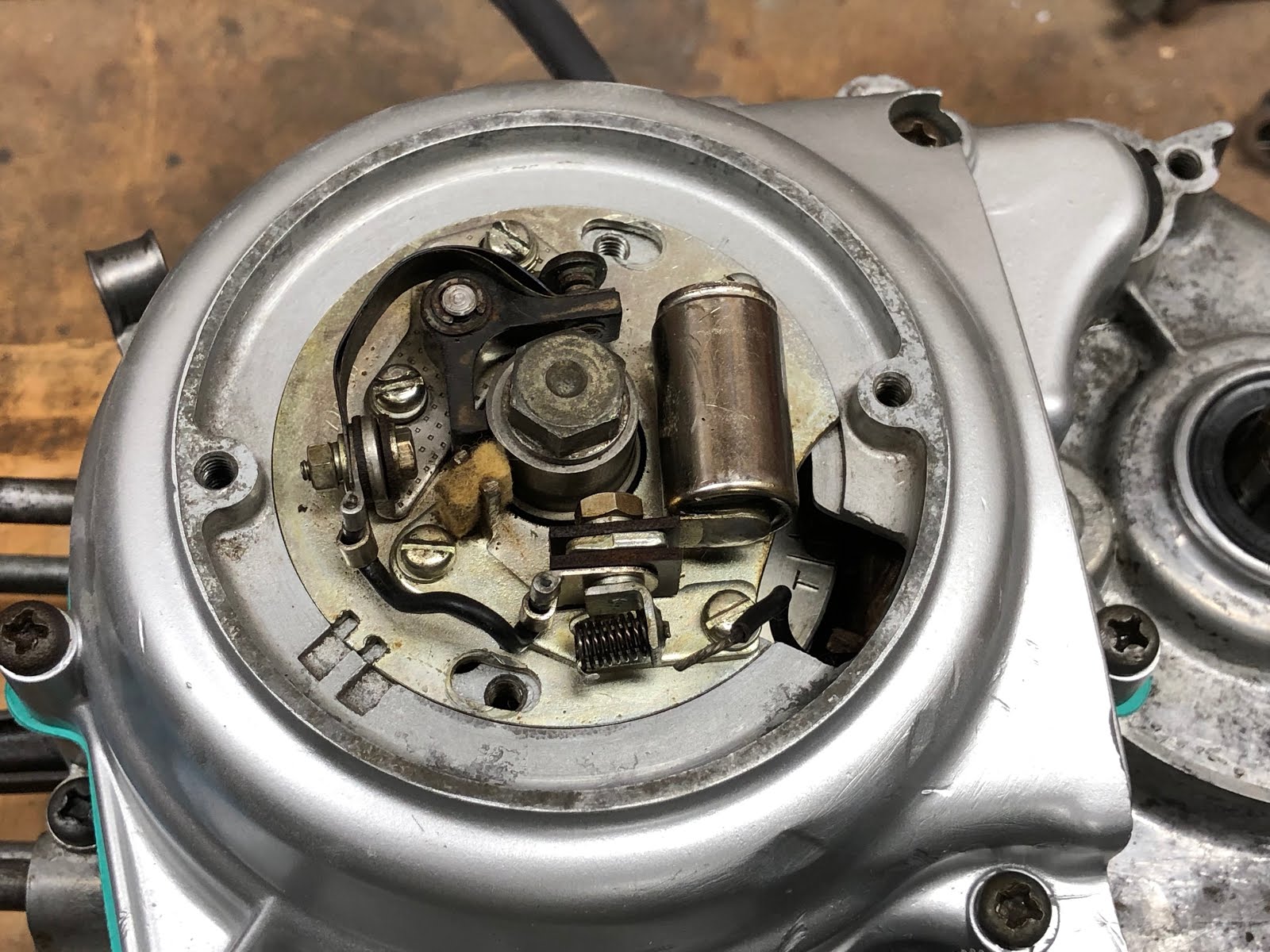
The next step is to install the points and condenser plate assembly.
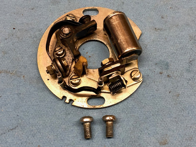
To install this assembly simply set it in place as shown in the pictures below making sure the wire that will go to the points is not trapped underneath.


Next install the two screws that retain the assembly, but leave them loose enough so the plate can still be rotated by hand.
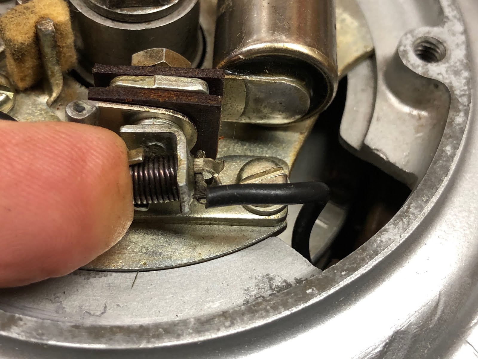
To attach the wire for the points, first depress the spring loaded wire retainer as shown in the picture below so that there is an opening for the wire. Insert the bare end of the wire and release.
The installation is now complete and we will come back later after the engine is fully assembled to adjust the points and set the timing.

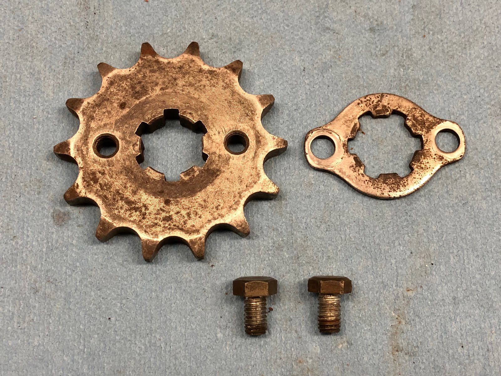
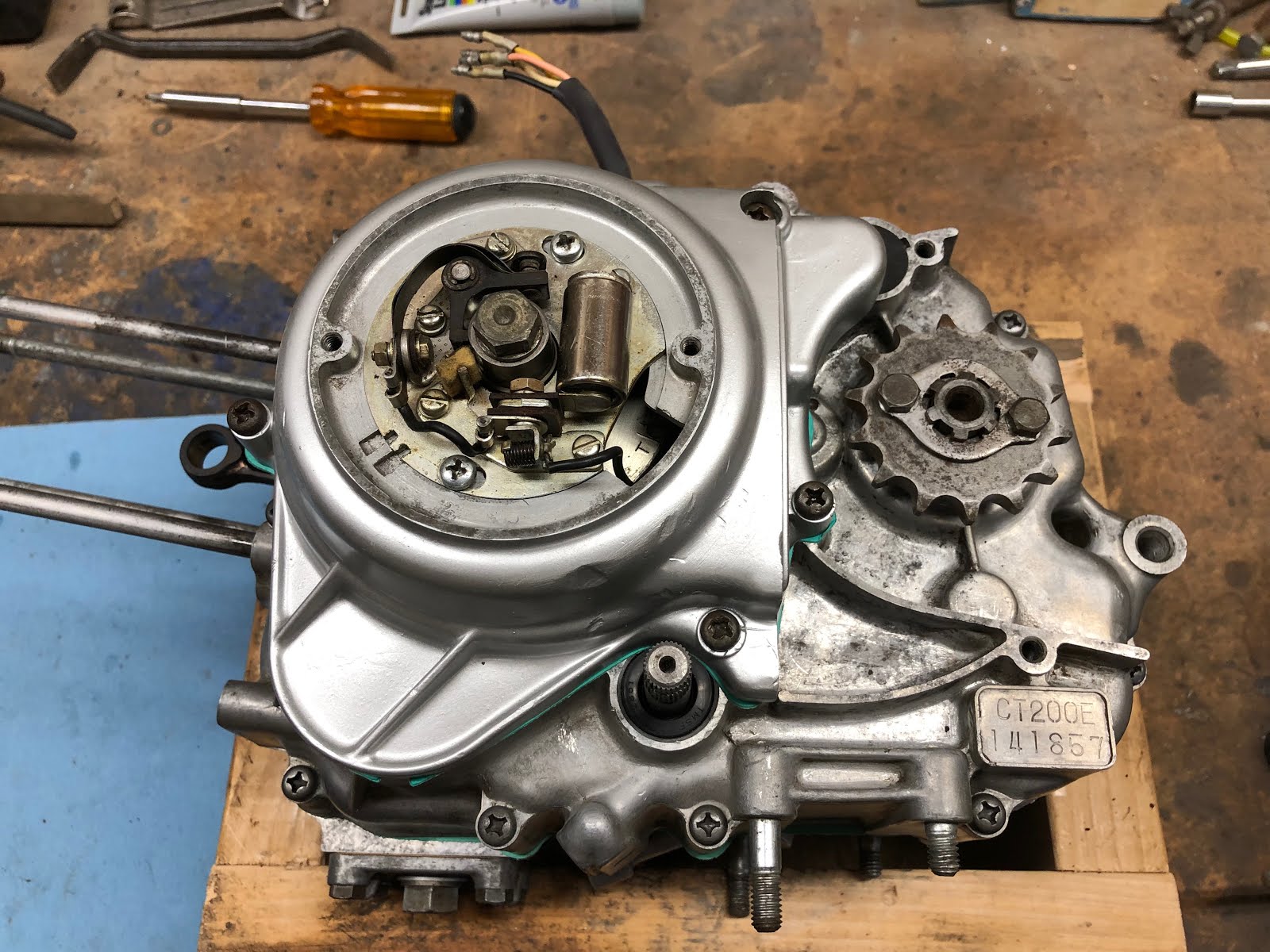
The next step is to install the drive sprocket.
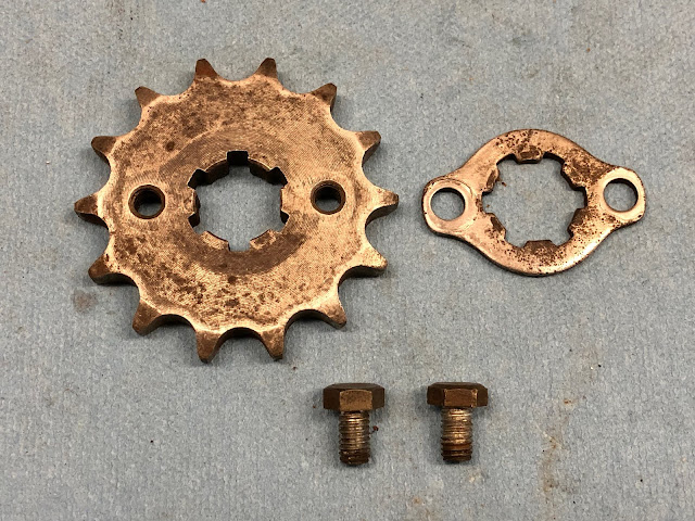
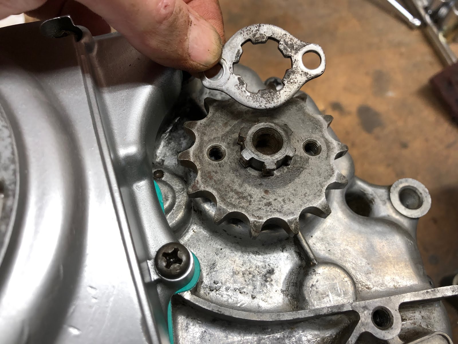
First slip the drive sprocket on the output shaft.


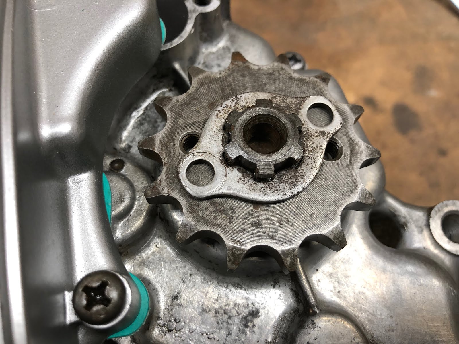
Next slide the retainer plate down over the splines of the output shaft until it is in line with the groove in the output shaft and then rotate the retainer plate in the groove until the holes in the plate align with the threaded holes in the drive sprocket as shown below.

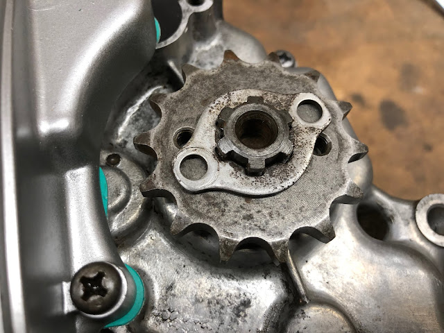

Lastly install the two short bolts that secure the drive sprocket to the retainer plate.

With that complete we will flip the engine over in the wood block so that we can complete the assembly of the right side of the engine.

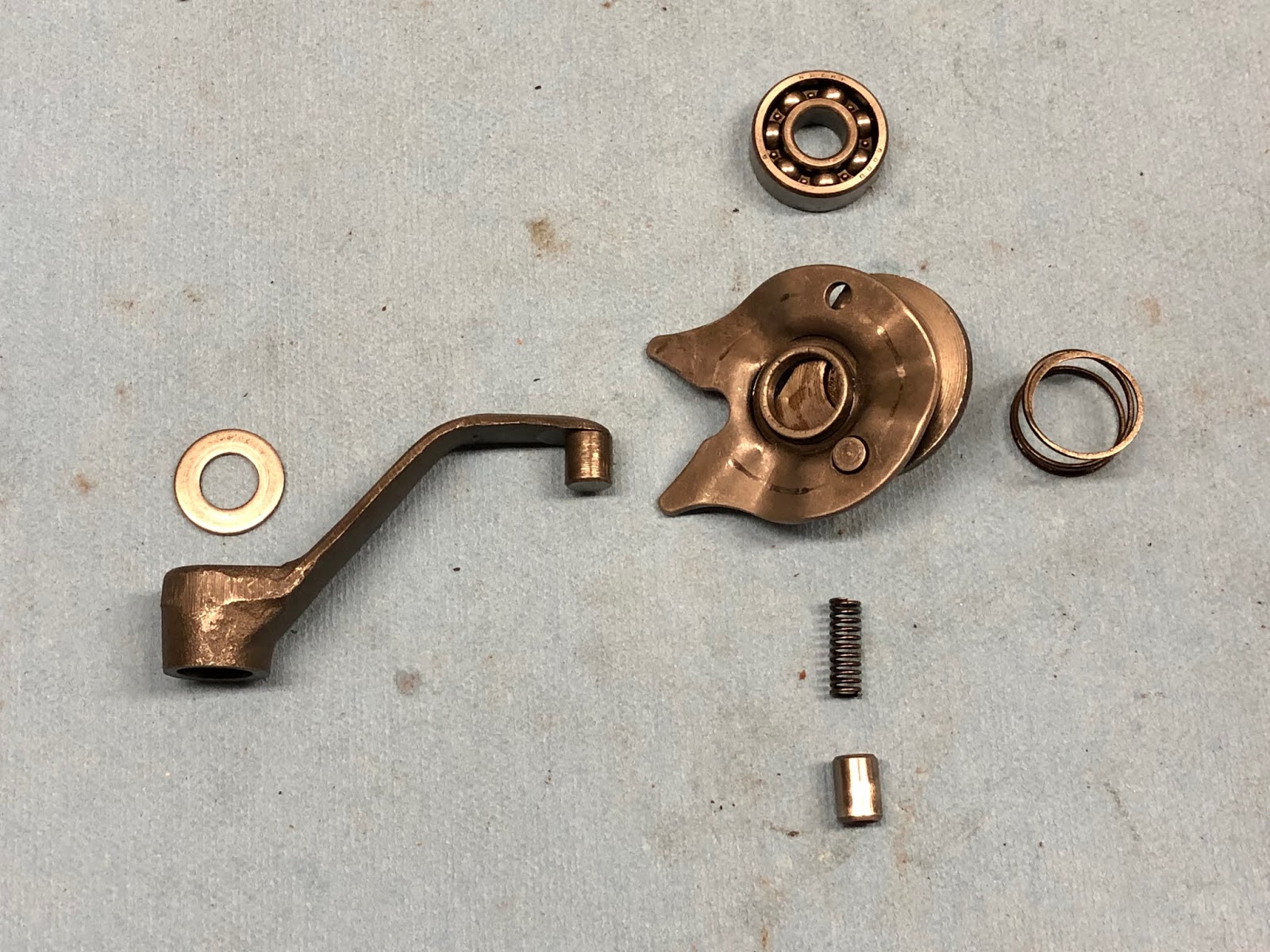
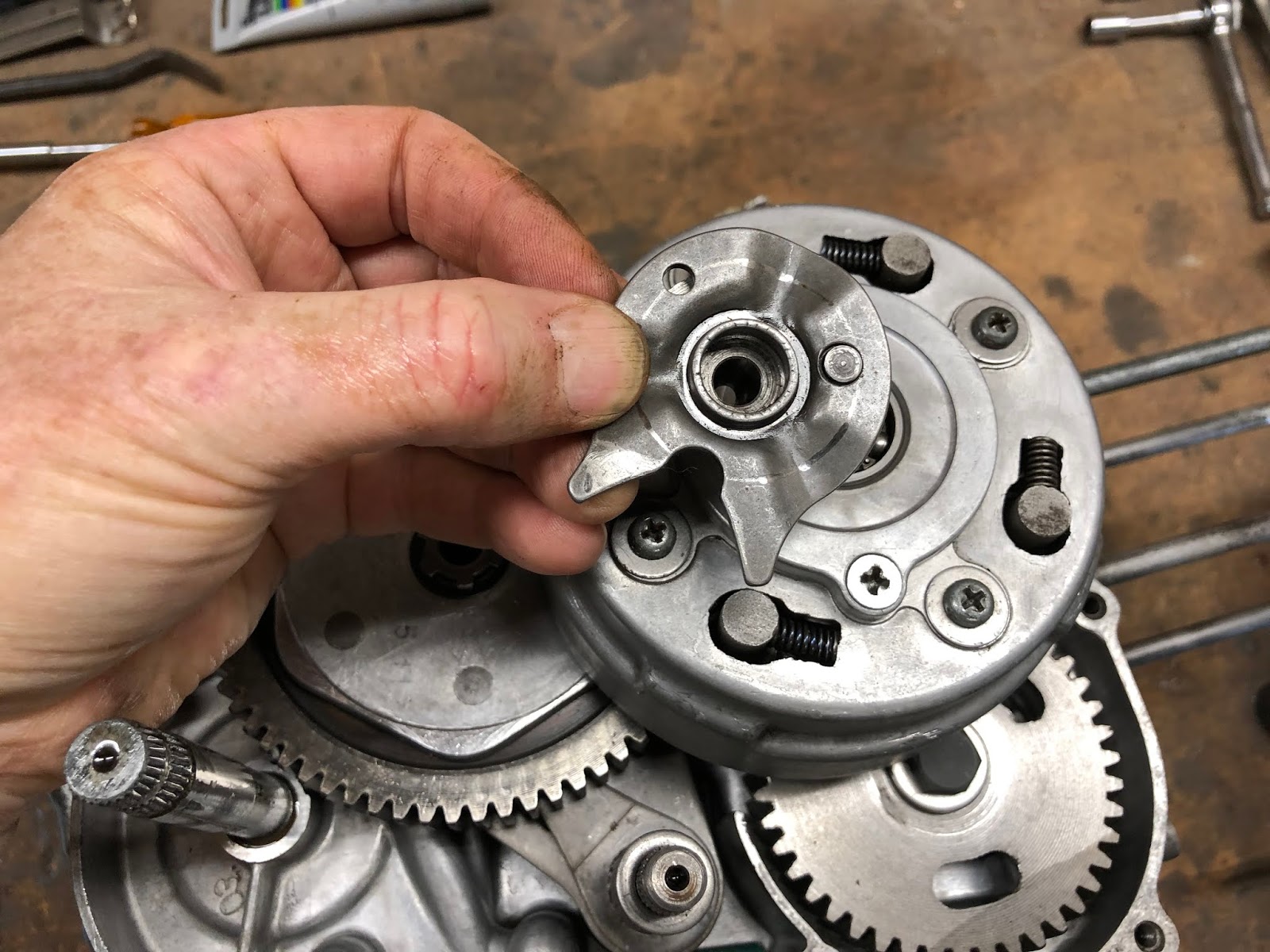
The next step is to assemble the components that actuate the clutch pack when you move the gear shift pedal.

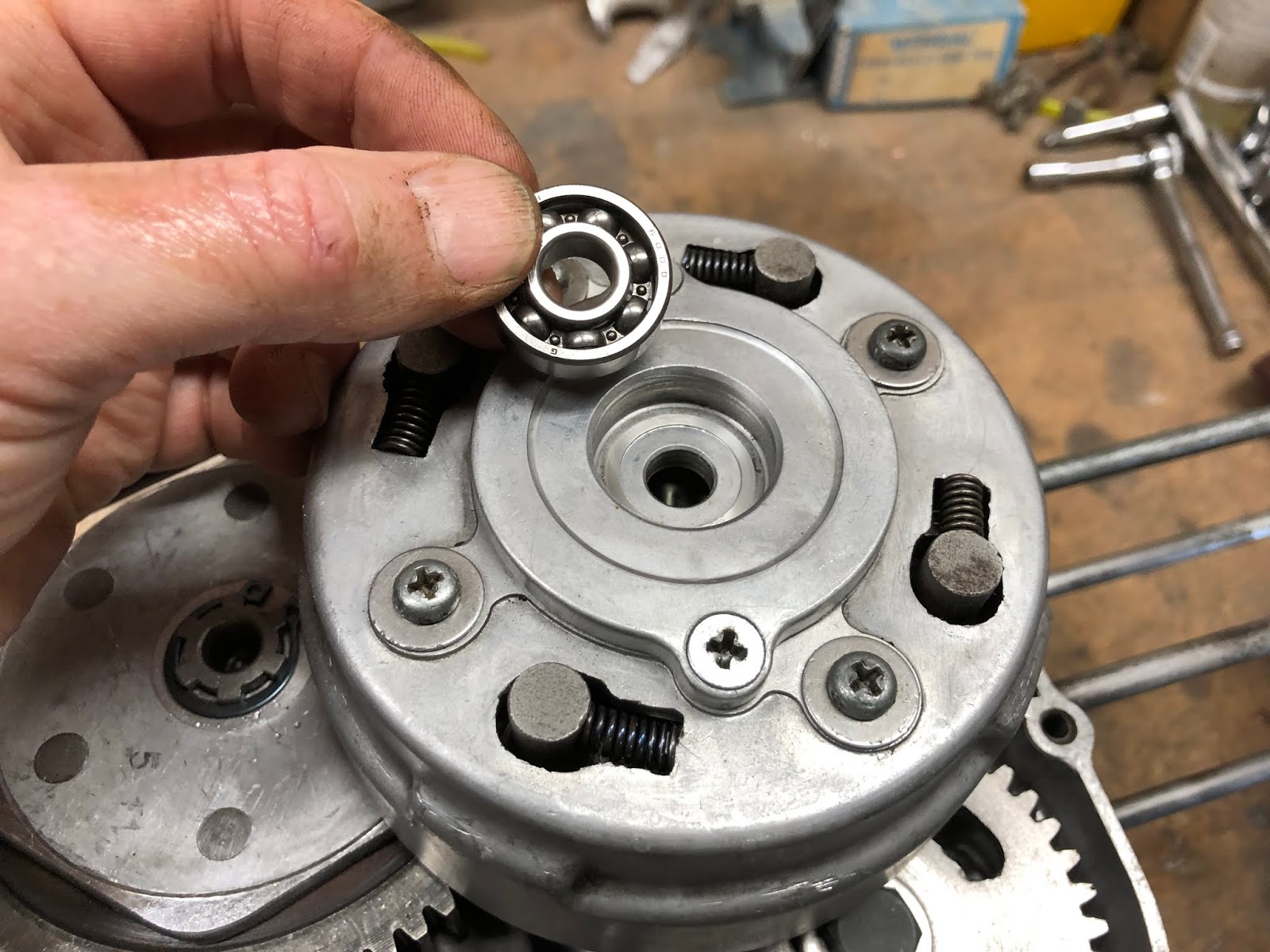
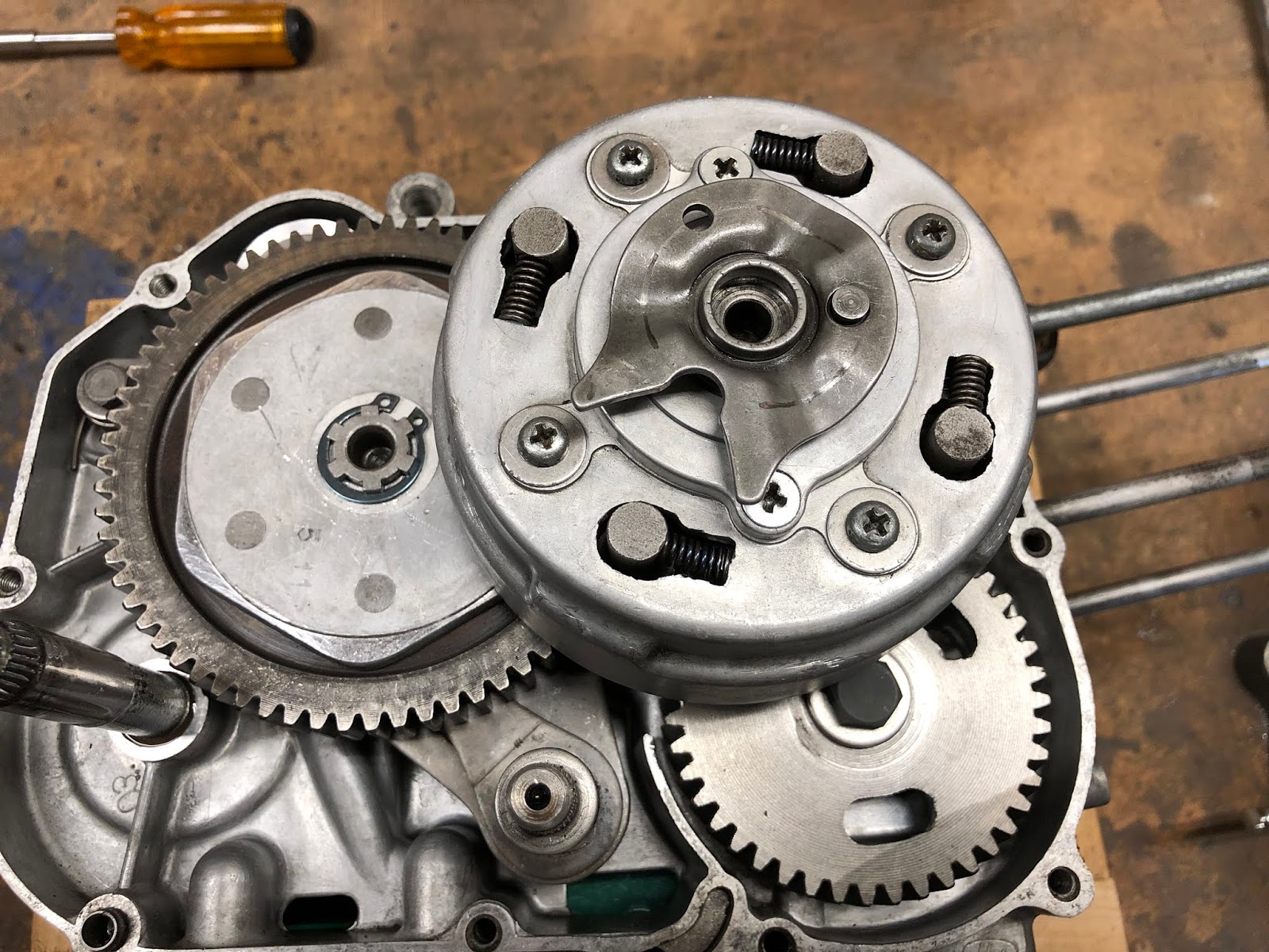
The first component to install is the bearing that goes in the bore on the end of the clutch pack.


That is followed by the ball-ramp assembly that slips into the inside diameter of the bearing we just installed.

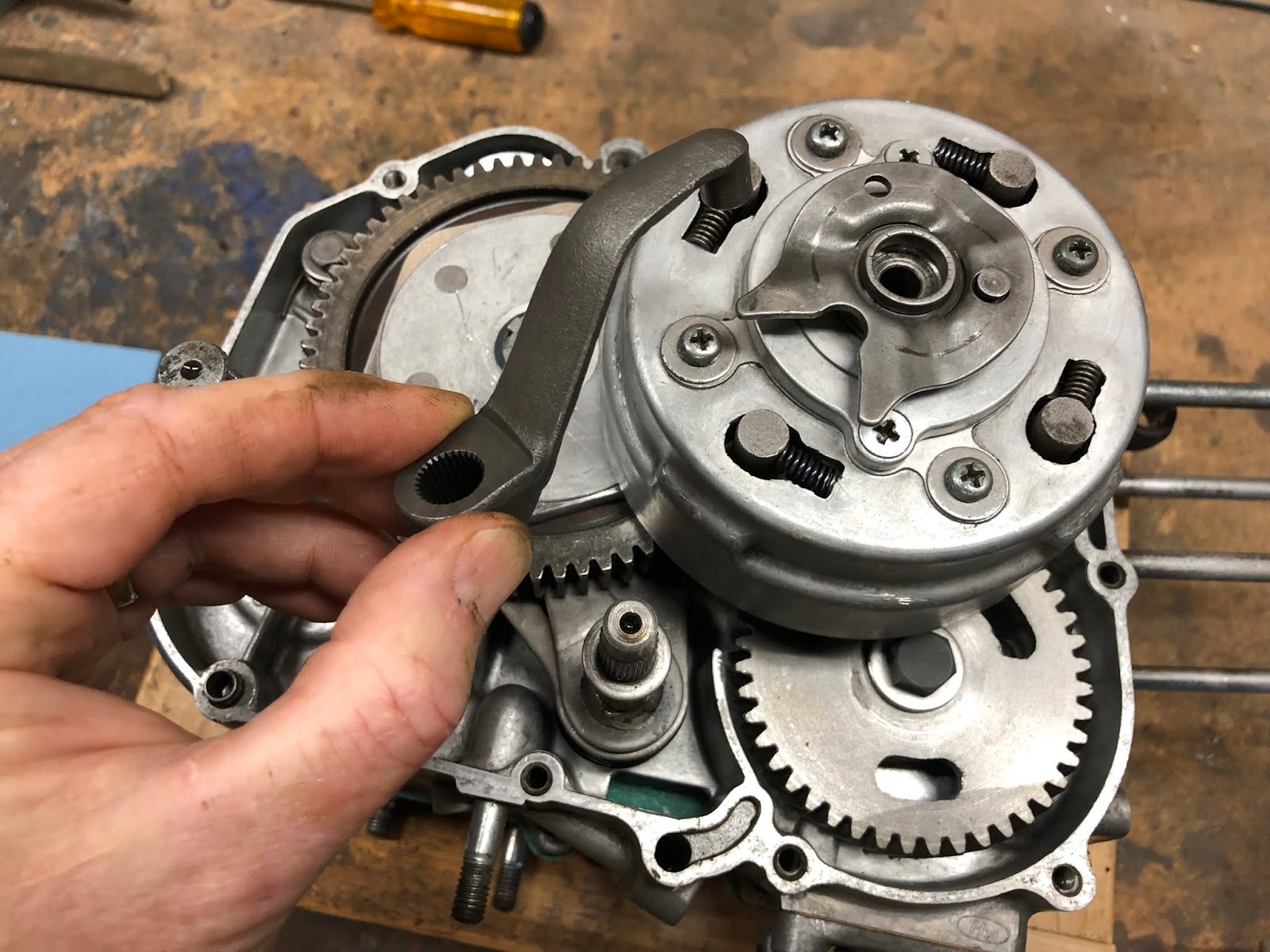
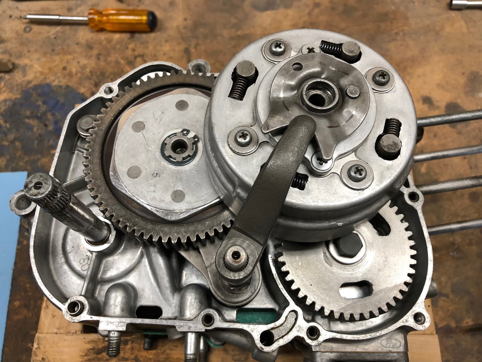
Next we will install the arm that slips on the gear shift shaft and mates into the notch on the ball-ramp assembly we just installed. The important detail with this step is to make sure the arm is pointing at the center of the clutch pack when it is installed.


The next step is to slip the thrust washer over the end of the gear shift shaft so it rests on the arm we just installed.


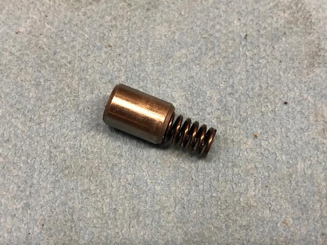
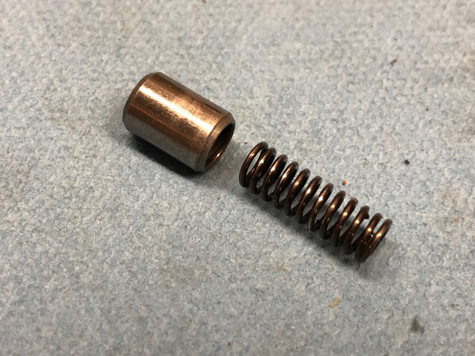
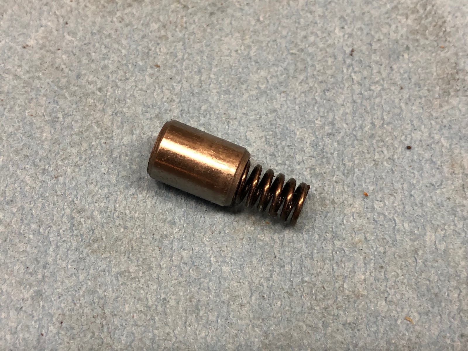
The next step is to install the small spring loaded plunger into the center of the ball-ramp assembly. First assemble the plunger on the spring and then drop it into the center of the ball-ramp assembly.


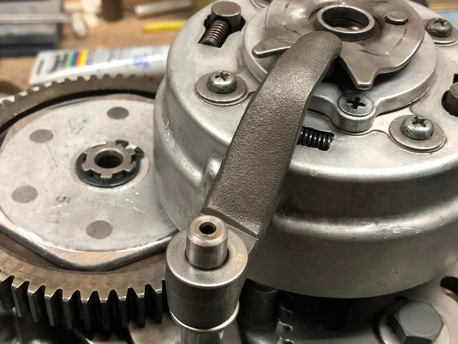
The last step with installing these components is to place the large diameter spring over the raised rim at the center of the ball-ramp assembly.


We will next install the right side cover, by first installing the appropriate gasket, then the cover and finally the screws that retain the side cover.


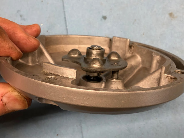
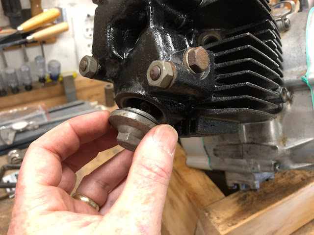
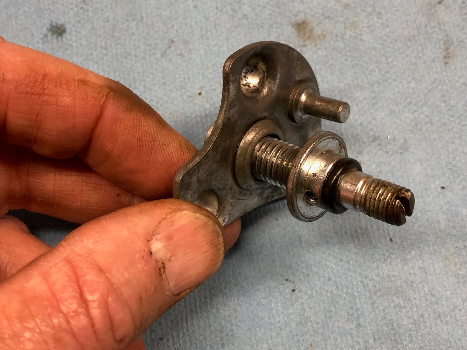
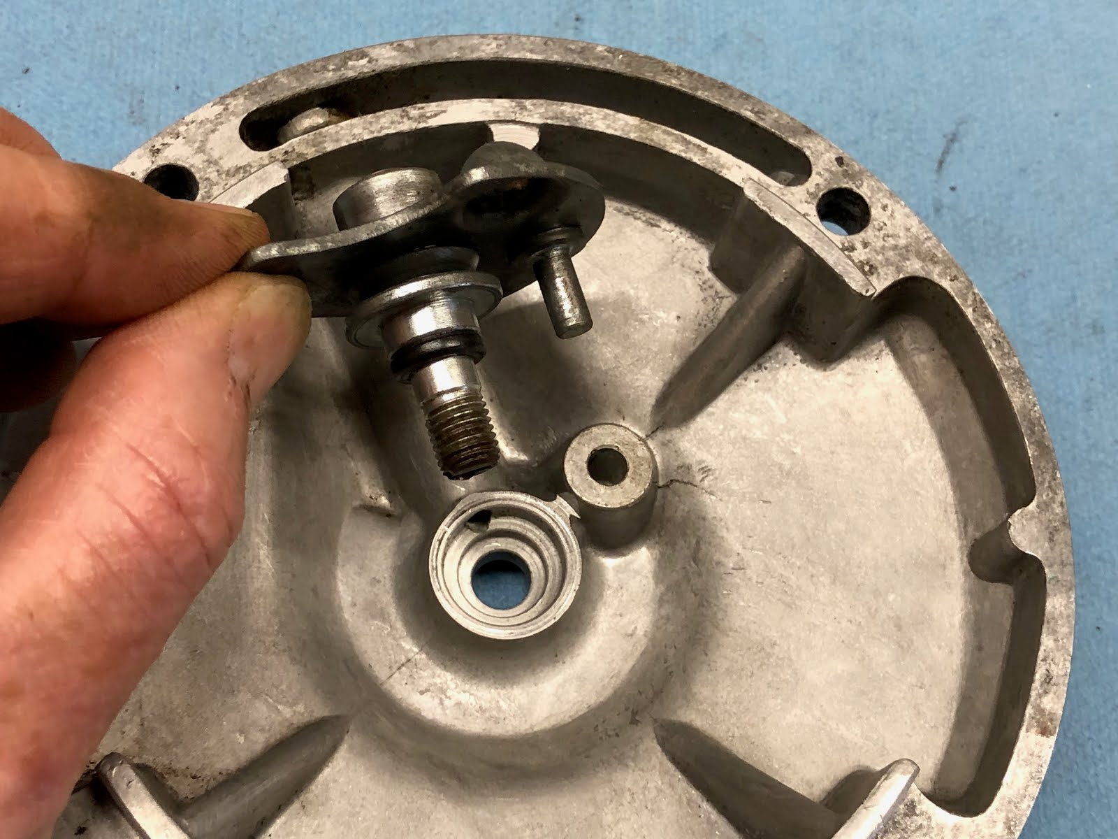
The final step to finish off the right side of the engine is to assemble the adjustment mechanism for the clutch to the cover and then install the cover.

First take the threaded shaft and thread it into the stamped ball plate as shown below and then insert into the cover making sure the get the anti-rotation pin in the bottomed hole on the back side of the cover. Its also important to make sure the o-ring is installed on the threaded shaft and this is another seal that didn't come in the gasket kit I purchased so don't lose the one that was on the shaft when you disassemble your engine.


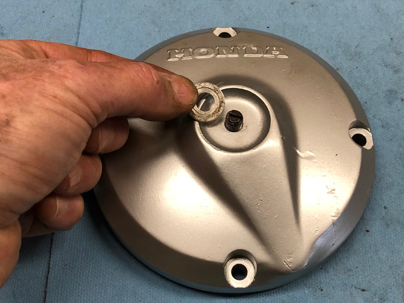
The last step to finish the installation of the adjustment mechanism to the cover is to install the washer and lock nut on the exposed end the the threaded shaft on the outside of the cover.


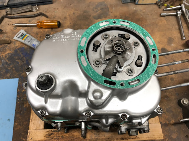
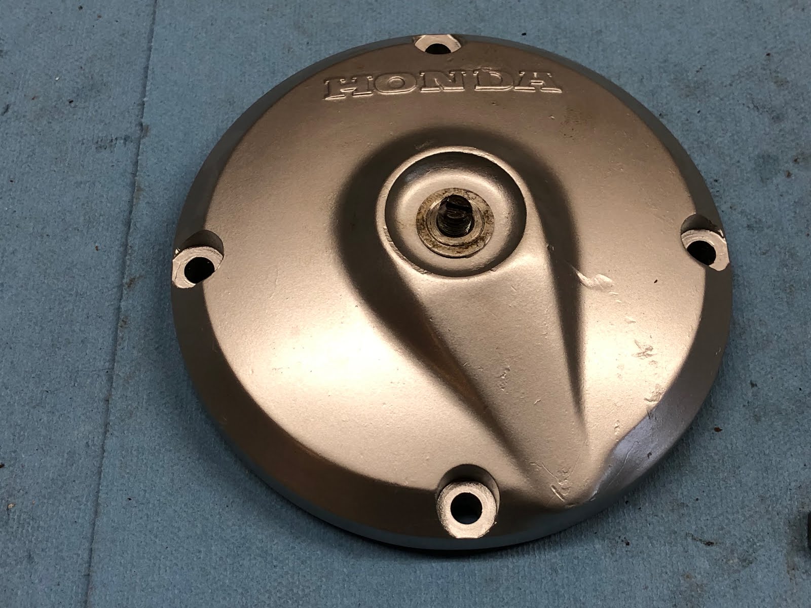
The next step is to install the clutch cover on the on the case by first installing the appropriate gasket, then the cover, and lastly the screws to retain the cover.

With the cover installed this is a good time to go ahead and do an initial adjustment of the clutch following the instructions in the Honda CT200 maintenance manual.
For the next step we will reposition the engine on the wood block and begin assembling the top end of the engine.
The next step will be to install the rings on the piston and then assemble the piston onto the piston rod.

We'll start with installing the rings on the piston. I'm not going to go into any detail about checking the end gap of the rings, etc. as I have never really bothered to check that on any bike or car piston I have installed over the last 45+ years and have never had a problem. Maybe I'm just lucky, but I think it is more that any automotive or motorcycle manufacture could never afford the time required to do that sort of check in a production environment and the focus is more on holding manufacturing tolerances tight so it won't be an issue.
I am also not going to try and explain in detail how to install each ring as there is a feel to it, so I'll just say that if you haven't done it before take your time and try not to break the compression and scraper rings as they are brittle. If you do end up breaking a ring well welcome to the club and now you with hopefully have the experience that you won't do it again with the next set of rings you have to buy.
On the page I have on video links I do include this link here which is a very nicely done video on how to install piston rings and is a good guide if you have never done it before.
Getting back to assembling this engine, there are there rings that need to be installed.
The top ring is the compression ring.
The next ring down is the oil scraper ring
And the bottom ring is the oil ring and can either be an assembly of three rings or is a single wide ring as is the case for this engine I am building here.
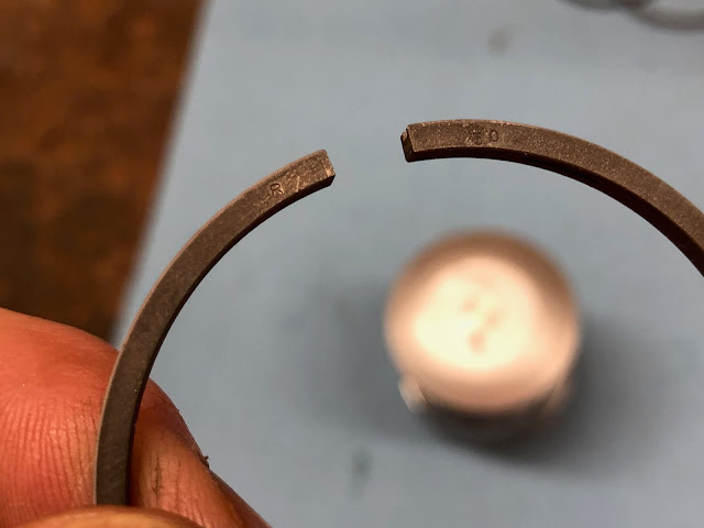
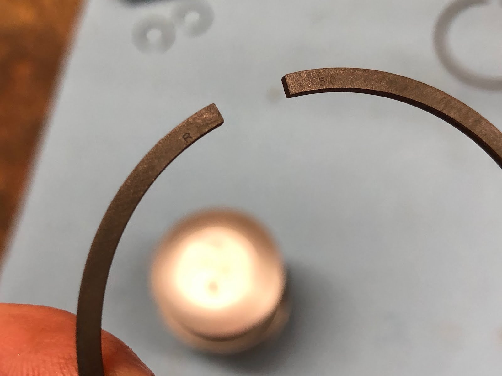
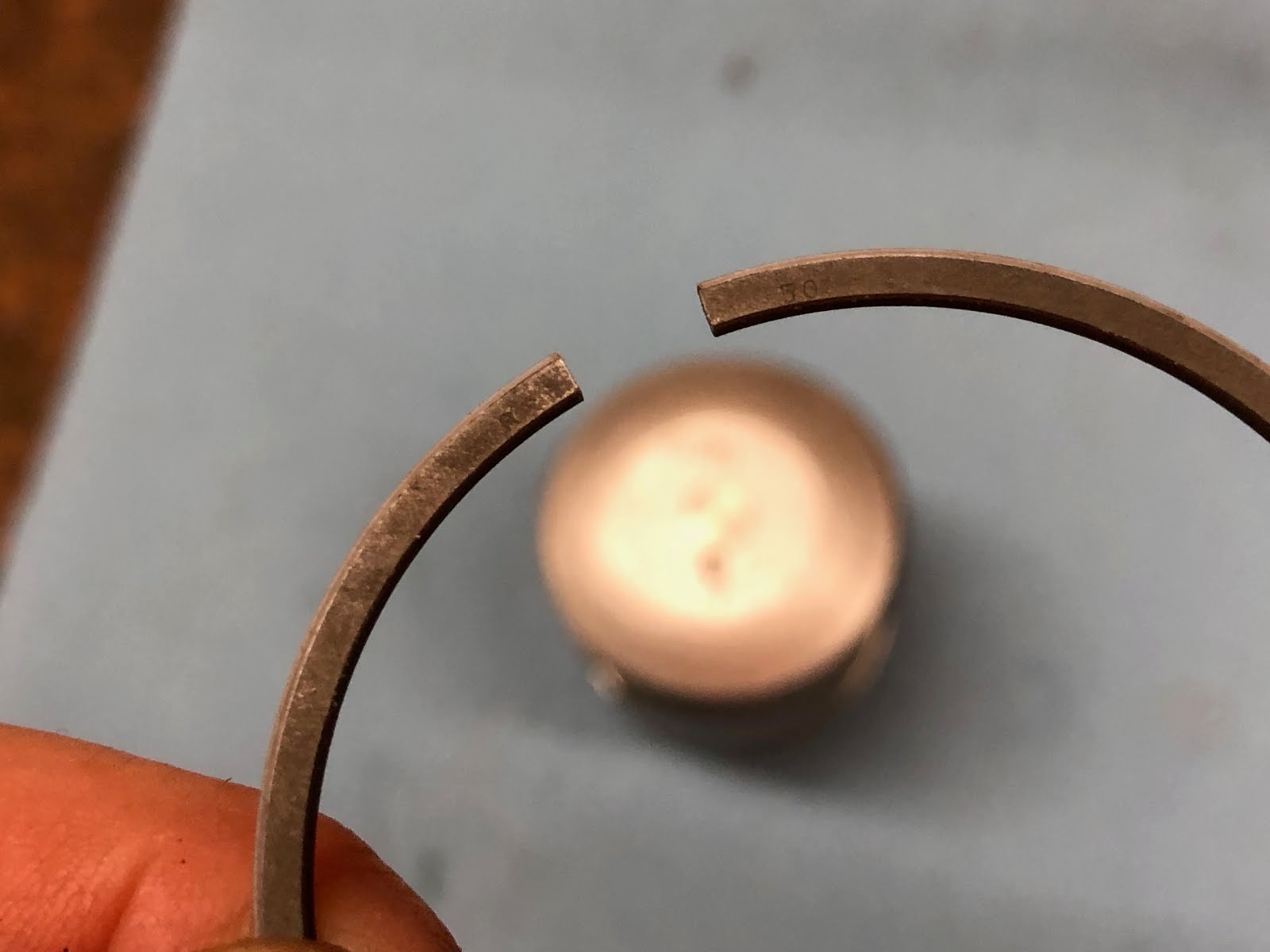
The first ring I will install is the oil ring and you will always want to install the lowest ring first and work up to installing the compression ring last. All rings will be marked something like what is shown in the picture below and the markings always face up towards the top of the piston.
And here is the oil ring installed in the piston.
Next is the oil scraper ring and agin install with the numbers facing up.


And the last ring to be installed in the compression ring agin with the markings facing up.

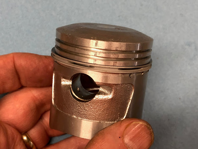
If you installed all three rings correctly it should look something like the picture below. When you actually go to install the piston in the cylinder you will want to make sure the gaps between all the rings are approximately 120 degrees apart and I prefer to have those gaps on either the left or right side of the piston and not directly on the top or bottom of the piston. Having the gaps staggered helps create a labyrinth seal for any gas that escape through the first gap in the compression ring.

The next step is to install the piston on the piston rod and the important detail here is to make sure the arrow on the top of the piston is pointing down as shown in the picture below.

To install the piston slide it over the end of the piston rod and align the bore for the wrist pin with the bore in the end of the piston rod and then slide the wrist pin through the piston and piston rod until it is centered.

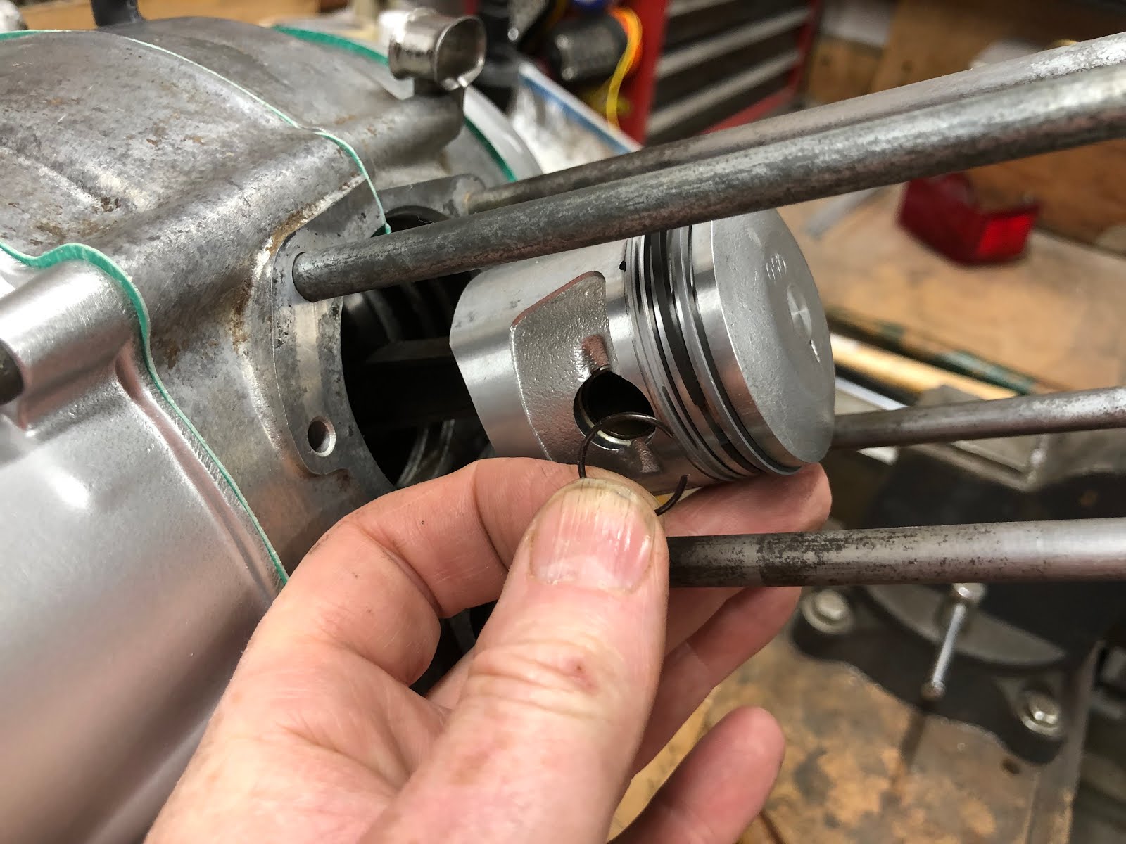
The last step is to install the small clip in each end of the wrist pin bore in the piston to retain the wrist pin.


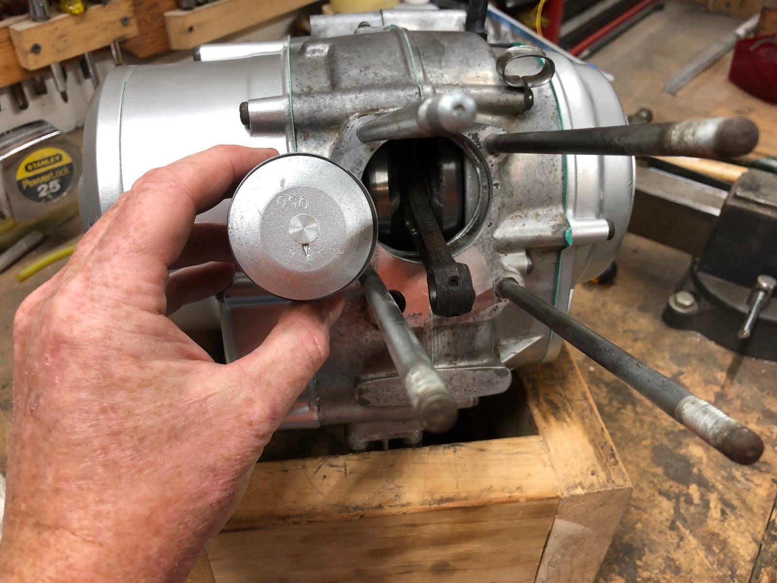
The next step is to install the cylinder.

First install the gasket over the studs and then start to slide the cylinder down over the studs to the piston.
At this point you want to check and make sure your piston rings are oriented correctly and I will tend to apply assembly lube to the bore, piston and rings.

The end of the cylinder that first engages the piston is chamfered to help with the installation of the rings. I will compress each rings with my finger and work it into the bore one at a time while also hold the piston as I slide the bore down. If you have a large oversize bore there may not be much of a lead in chamfer left, but if you keep at it you'll be able to get the rings compressed and in the cylinder.

Another way to help hold the piston as you try and slide on the cylinder is to put a 14mm wrench on the head or the bolt for the rotor and spark advancer as shown below.

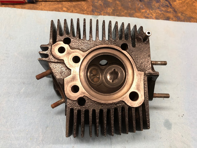
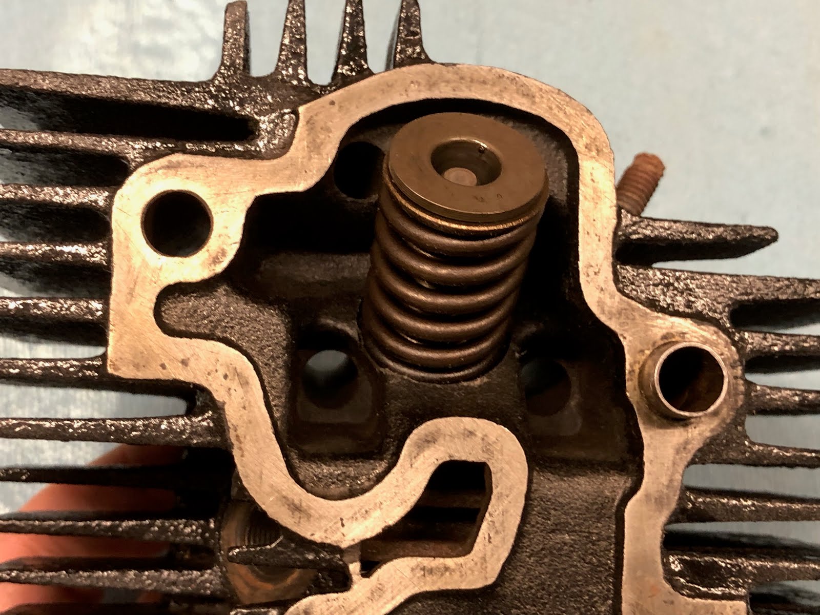
The next step is to build up the cylinder head.

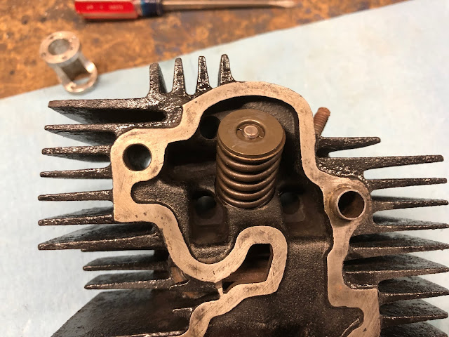
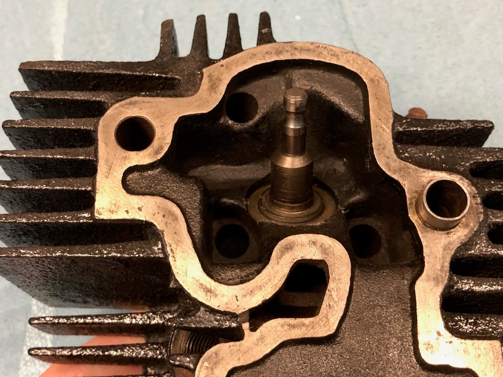
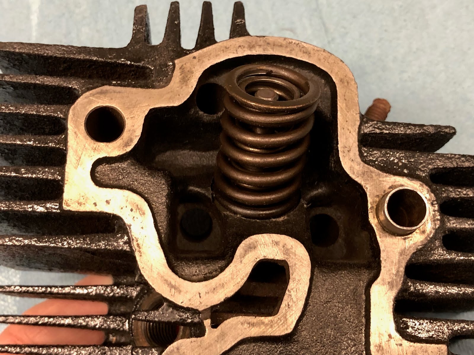
To install the exhaust valve, lubricate the stem and then insert it into the correct hole in the cylinder head. Then on the other end install the inner spring, outer spring and cupped washer that will retain the valve stem retainers.


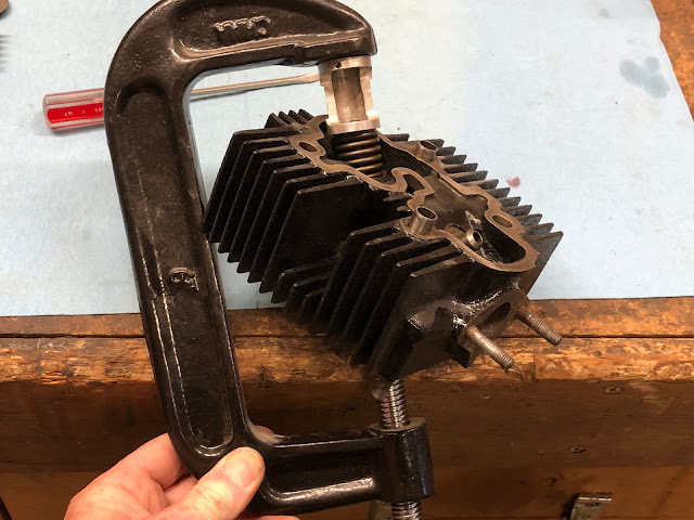
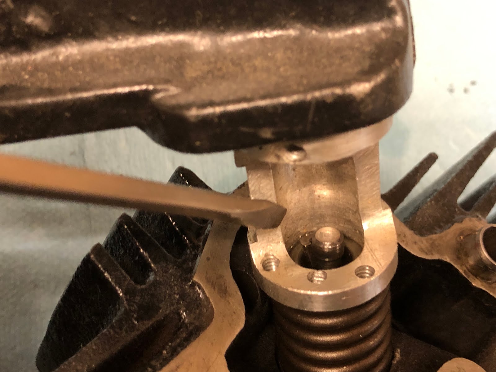
The next step is to use a valve spring compressor to compress the springs so that the valve stem retainer clips can be installed.
I use a simple tool that I made which utilizes a C Clamp that does the job. I made a post on the method and tool I use here at the following link.

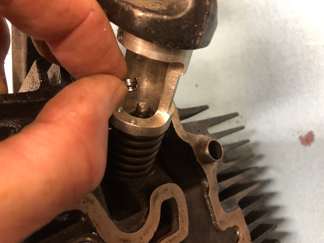

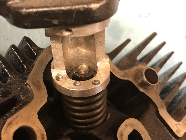
With both retainers installed, remove the spring compressor and the installation of the valve is complete.
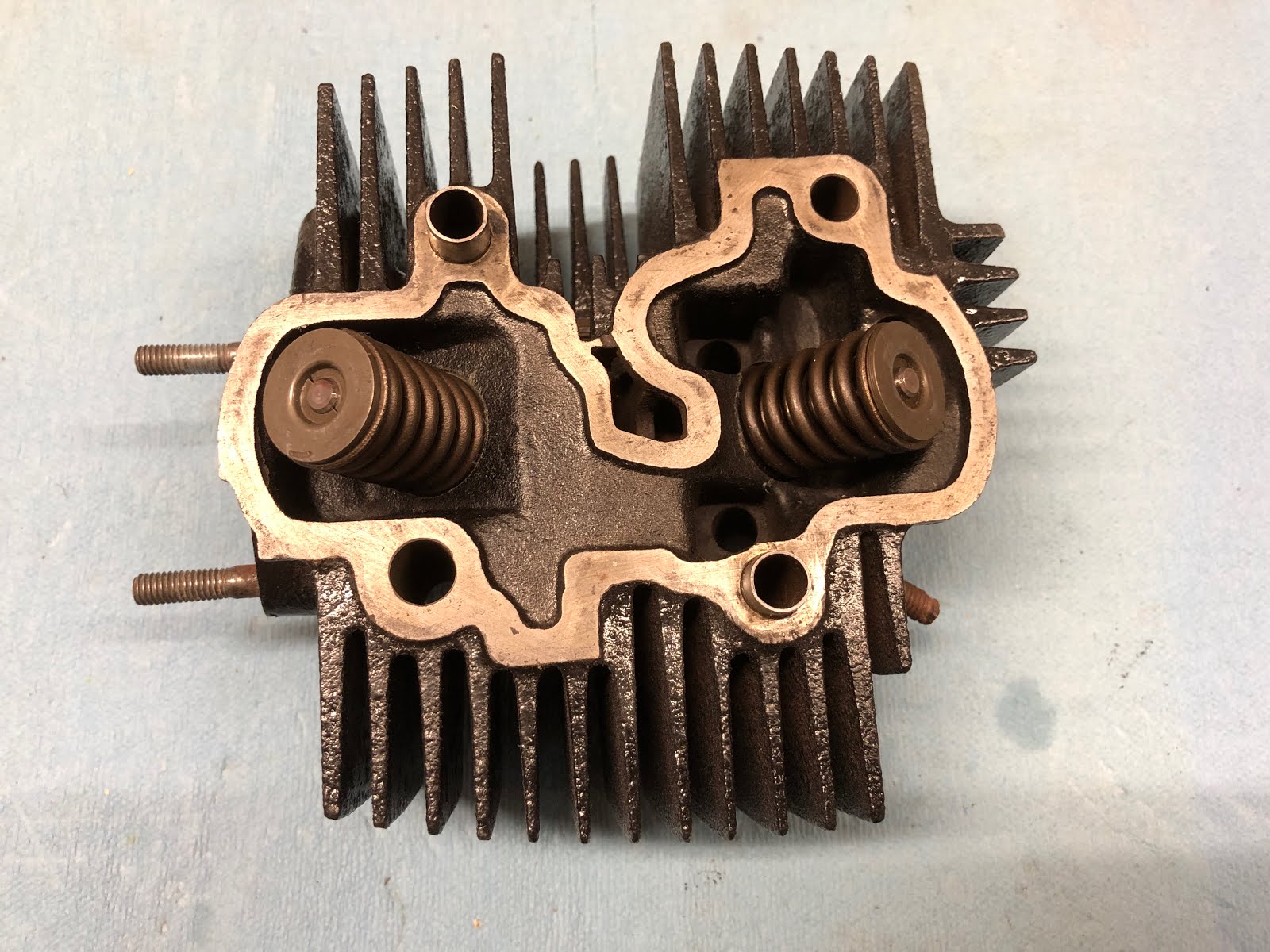
Repeat the exact same steps with the intake valve and then the cylinder head assembly will be complete.

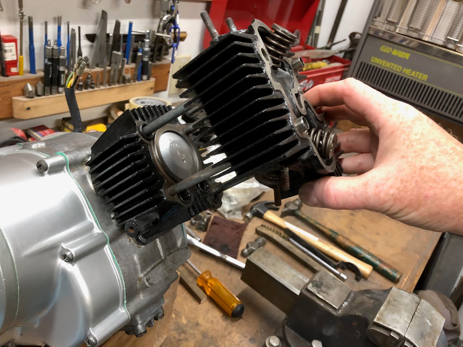
The next step will be to install the cylinder head and associated seals on the engine.

for this step it can make things easier if we first re-orient the engine in the wood block so that it is pointing up which will help keep several of the small seals in place during their installation.

Another assembly aid is to apply a very small amount of the assembly lube to each seal as it is a sticky lube and will help hold each seal in place.

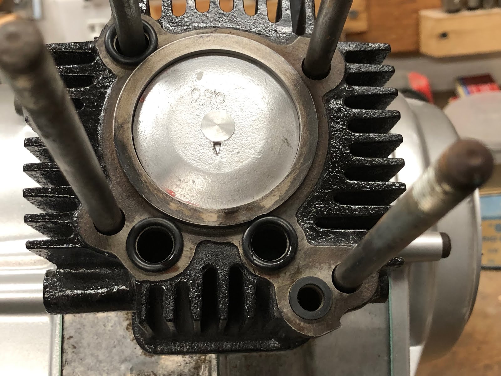
Install the three o-rings in there respective positions as shown in the picture below.

Next install the square cross section o-ring in the lower right position as shown below.


The last step before installing the cylinder head is to position the head gasket. I will use small amounts of the assembly lube on the head gasket to help it stick to the cylinder head while it is being lowered into position as shown below.


With the cylinder head now in position holding all of the seals in place the engine can be re-oriented in the wood block for the next step where the rocker arm assembly will be installed.

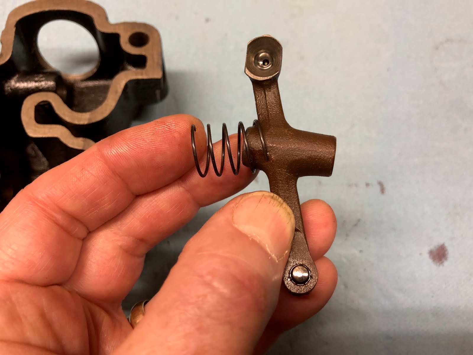
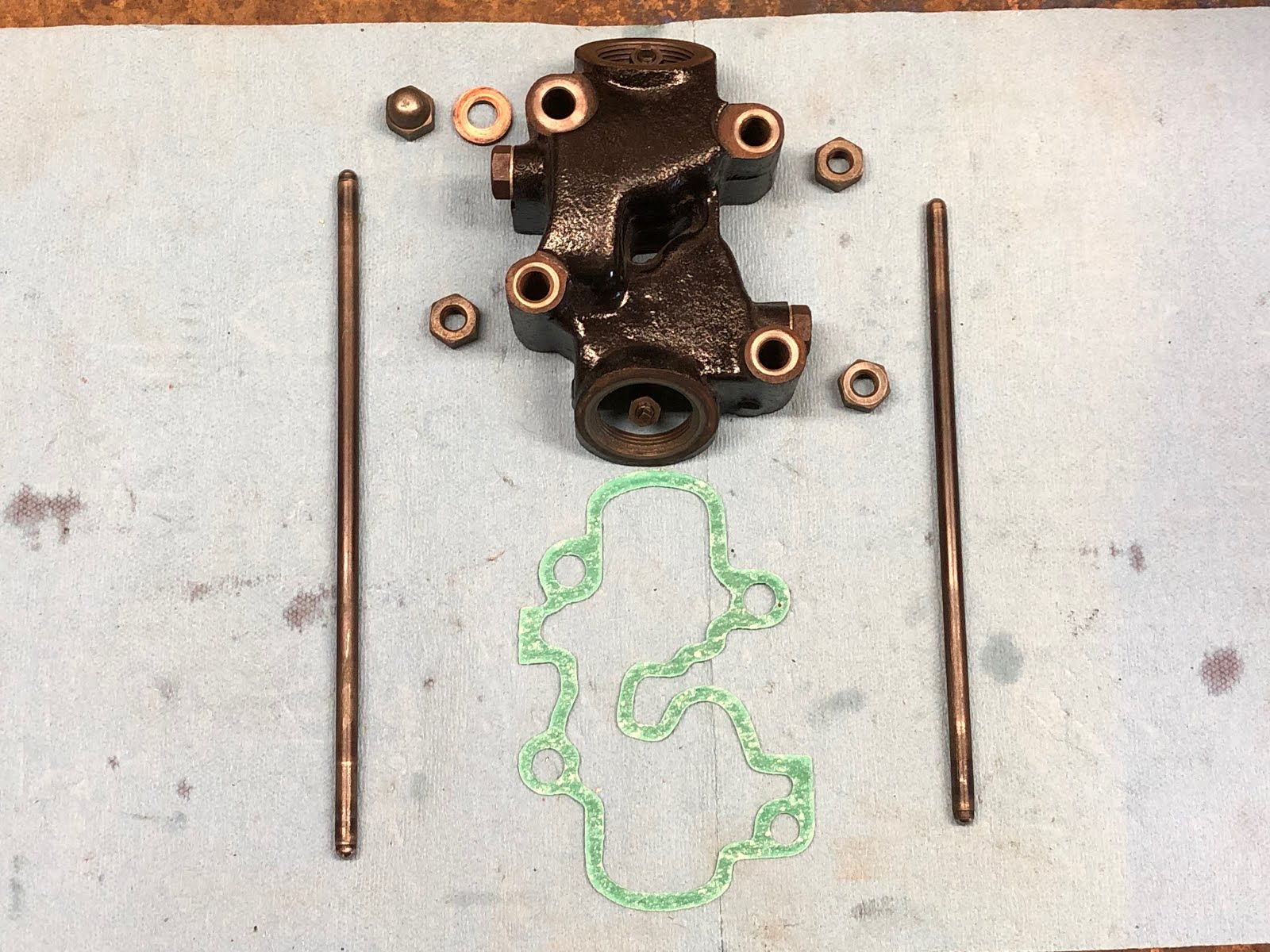
Here are the components that make up the rocker arm assembly. Its also a good idea at this point to set the adjustment screws on each rocker arm so they are at their loosest setting which will make it easier later on when we go to adjust the valves.

Starting with the longer rocker arm, assemble the spring to the hub of the rocker arm as shown below and then compress the spring and place the rocker arm and spring into the housing with the spring facing the opening that the rocker arm shaft will be inserted through.


Next install the shaft for the rocker arm with a little assembly lube or oil into the bore until it is fully seated.


The next step is to install the short bolt and aluminum washer into the opening that you just installed the rocker arm shaft through and tighten the bolt.


The next step is to follow the same process to install the shorter rocker arm & spring, rocker shaft, and bolt and aluminum washer.


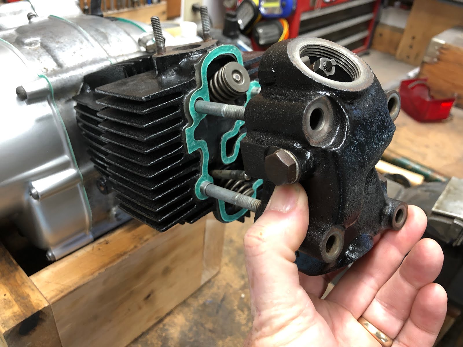
The next step is to install the rocker arm assembly on to the engine.

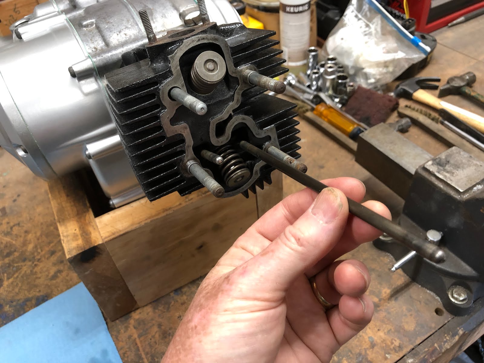
We first will install the push rods with the long push rod installed into the left hole as you're facing the engine and the shorter push rod being installed in the right hole.


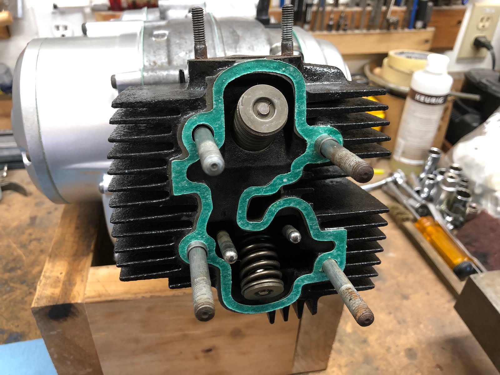
Next install the gasket for the rocker arm assembly as shown below.

Then install the rocker arm assembly over the mounting studs.


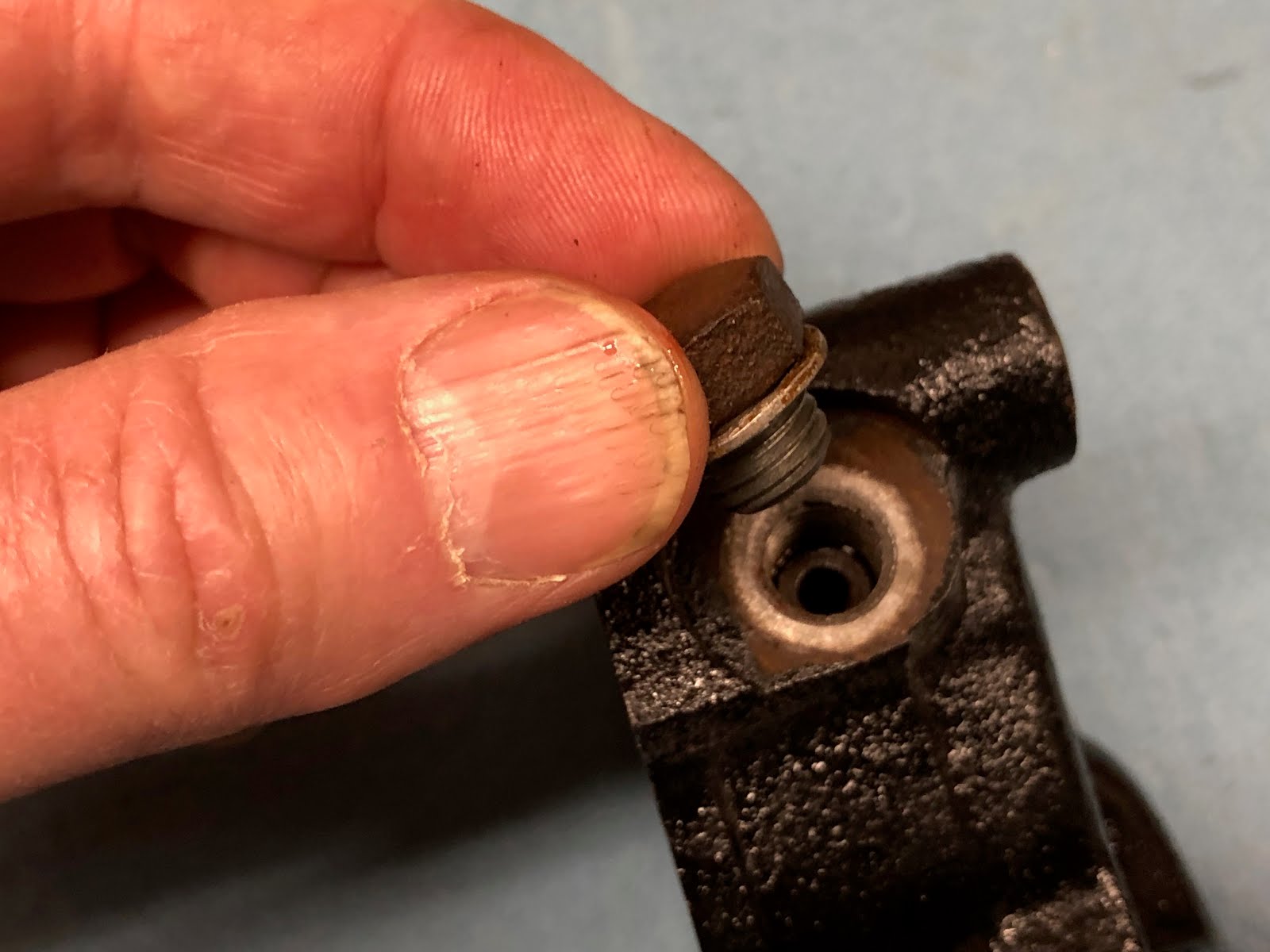
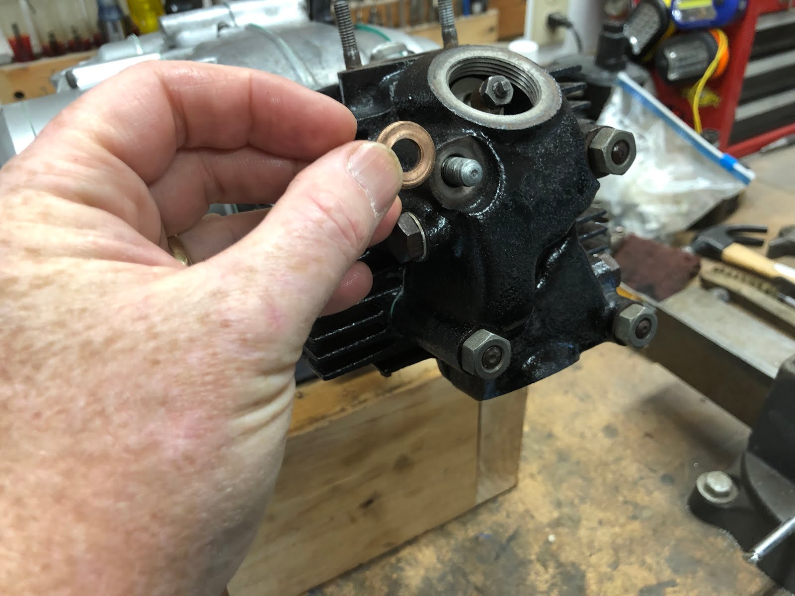
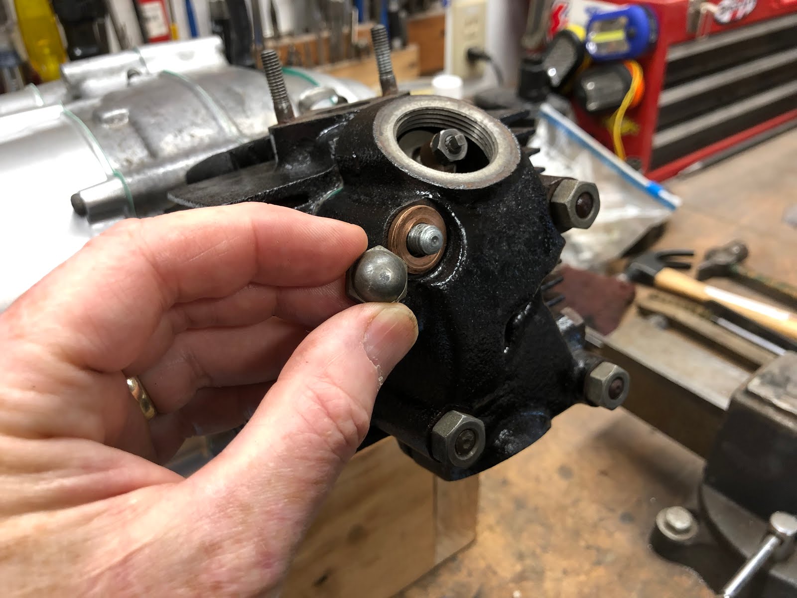
Next install the nuts that retains the top end paying attention to make sure that the copper washer and cap nut are installed on the upper left stud as shown in the pictures below. The copper washer acts as an oil seal for the pressurized oil that is being supplied to the cylinder head and rocker arm assembly along this stud.


The final step is to torque these nuts to the value specified in the Honda manual and also following the pattern defined in the manual.
With the basic engine assembled, we will now turn our attention to making some final adjustments to the valves and points and then setting the timing before installing the final covers.
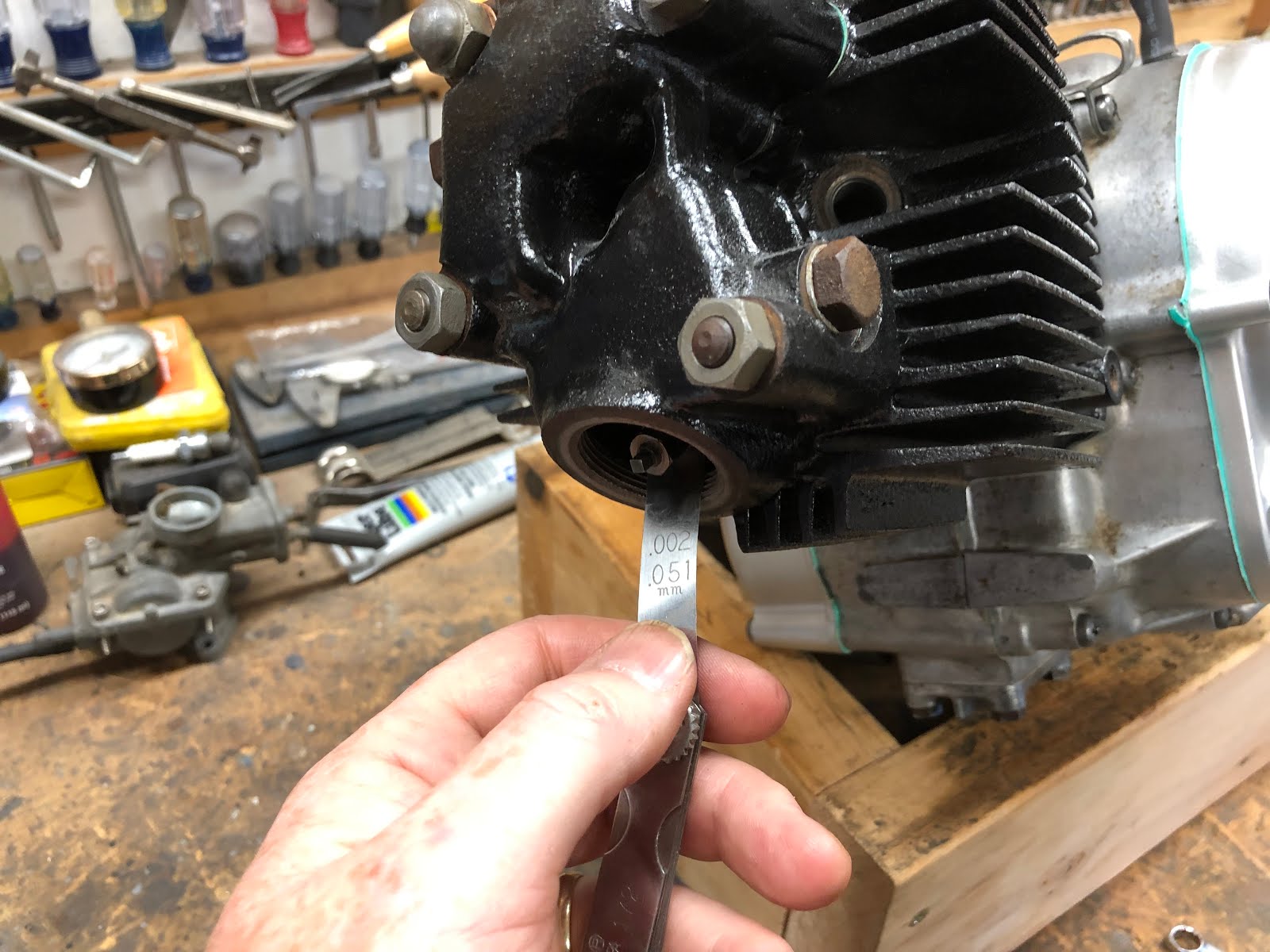
The first thing we will do is adjust the valves and to do this we turn the crank as needed so that the piston is at top dead center on the compression stroke. When you are at top dead center on the compression stroke the timing pointer should be pointing at the mark next to the "T" on the alternator rotor as shown in the picture below and both rocker arms should be slightly loose.

With the engine at top dead center adjust the intake and exhaust valves so there is .002 inches of clearance. Standard practice is to use a feeler gauge to set this gap, but if you are in a pinch and don't have a .002 inch feeler gauge you can screw down each post until it just touches the top if the valve stem and then back it off 1/8 of a turn and that will leave you a gap of about .0024 inches.
Once you have each gap set, tighten the lock nut while holding the adjusting screw/post.


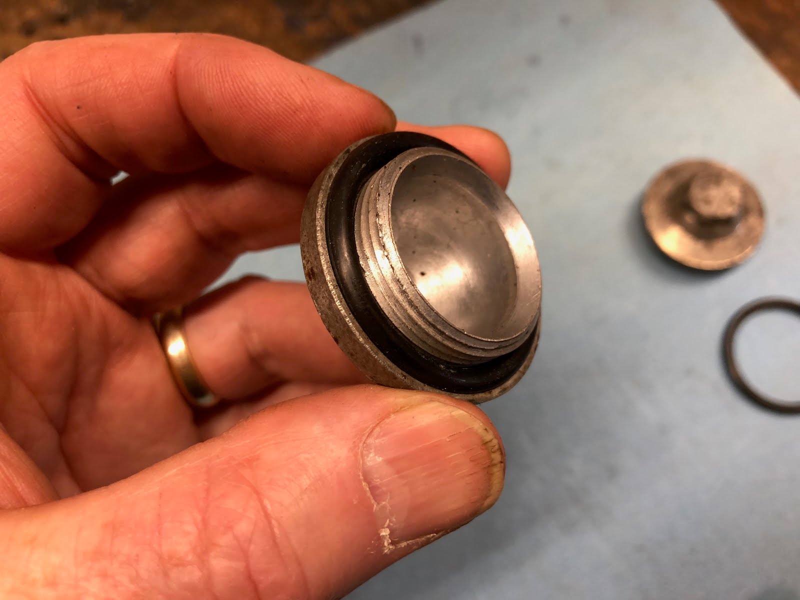
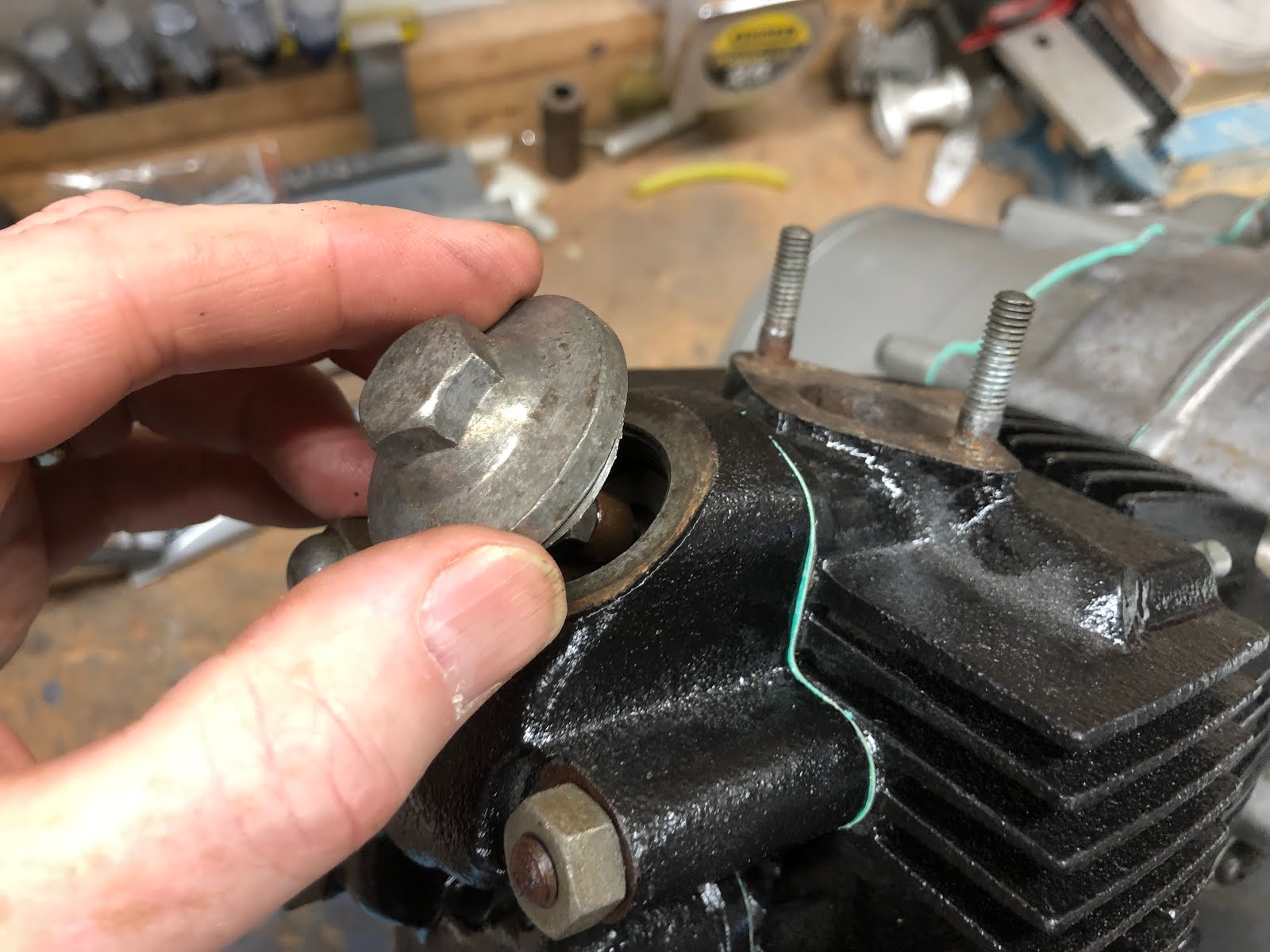
With both valves adjusted, its time to install the two valve access caps.
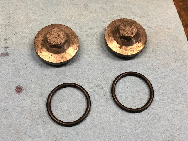
Install a new o-ring on each cap as shown and the install into threaded openings on the rocker arm assembly.


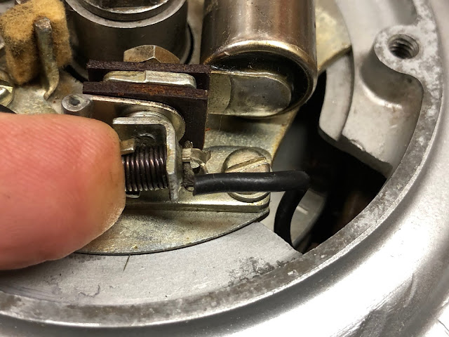
With the valves adjusted the next step is to adjust the gap on the points assembly.
To Adjust the points to the correct gap we first need to rotate the engine counterclockwise using a 14mm wrench on the head of the bolt holding the spark advancer until the gap on the points are at their widest position.
At this position we use a feeler gauge to check the gap and see if it is in the range of .012 to .016 inches. While any gap in the range is acceptable, I generally shoot for the lower end as it allows more time to saturate the coil at higher RPM's which helps ensure a good strong spark.
This is also a good time to clean the contacts on your points if the are not flat or clean. If you do feel you need to file your points go very easy and remove the least amount of material possible and the clean with contact cleaner so that they are clean and dry when you are down.
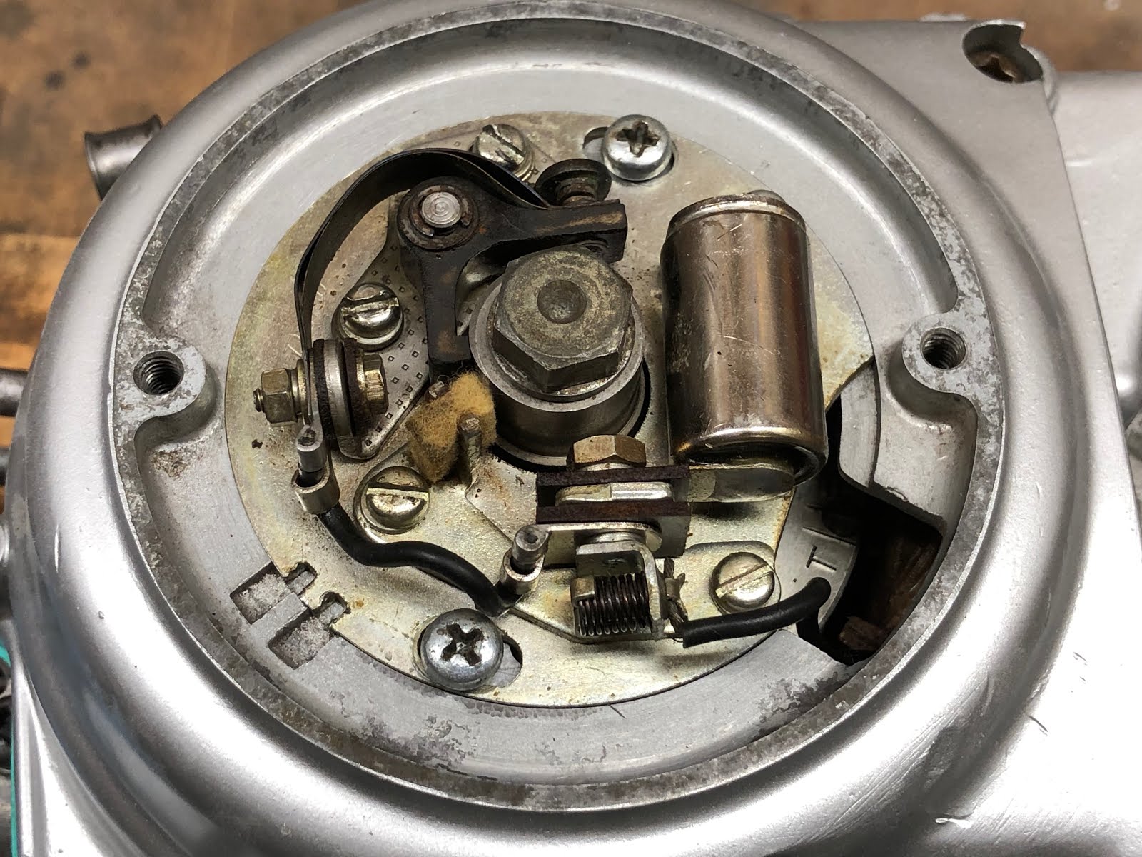
The following picture points out the key features related to adjusting your points gap.

So, again use a feel gauge to check the gap as shown below.

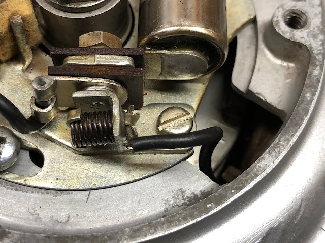
If you need to adjust the gap, slightly loosen the two mounting screws as shown below.


Then turn the small adjuster feature until you have the desired gap and then tighten down the two mounting screws. It is always a good idea to recheck the gap after tightening the mounting screws to see if you still have the desired gap.

Your points may look slightly different then the points shown in the pictures above as Honda used more then one supplier for points assemblies, but the process should be similar for other brands of points.
This is also a good time to add a very small amount of lubricant to the felt pad where it contacts the cam on the spark advancer. The lubricant helps minimize the wear of the leg of the points that rides on the cam. I use the lube shown in the picture below and I use it very sparingly as I do not want any of the lubricant to ever make its way to the actual points contacts.

The last major step before we can finish the assembly of the engine is to adjust the timing.
At a minimum you will need a static timing light to set your timing and I have a post where I shown how to make a basic static timing light from a almost free Harbor Freight LED light at the link here.
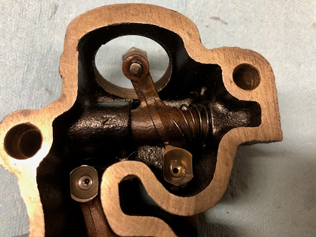
The following picture points out some of the key features involved with adjusting your timing.

The picture below is how I connect my static timing light. One lead from the light goes to the black wire in the engine harness coming from the points and the other lead from my light goes to a ground on the engine. When the points close the light should come on and when the points open the light should go off.

With the static timing light connected if your timing is set correctly then the light should go off just as the line next to the "F" comes in line with the line on the pointer while rotating counterclockwise on the compression stroke.
If your timing is a little off one way or the other, loosen the two screws that clamp down the points plate so it can rotate as shown below.

Then use a blade screwdriver in the adjusting slot to rotate the points plate either clockwise or counterclockwise to get the timing light to go off just as the line next to the "F" comes in line with the line on the pointer.

Once your timing is finally adjusted correctly it should look like what is shown in the following video.
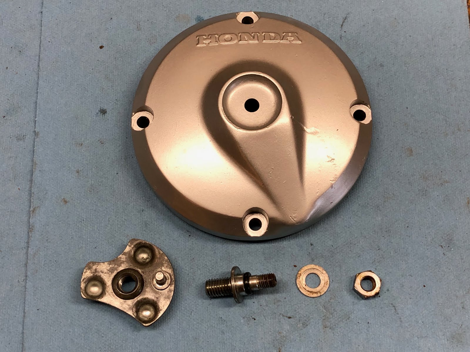
With the timing complete its time to complete the assembly of the engine by installing the remaining parts shown below.
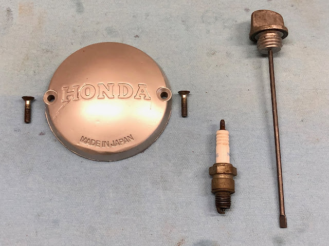
The access cover has an integral molded rubber gasket and installs with two screws.


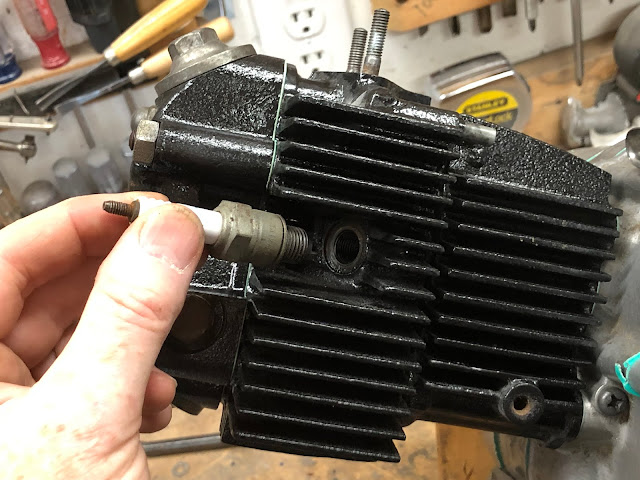
Next install the spark plug.
And lastly install the oil fill cap/dipstick.

And with that the engine is now complete.

With this engine I will add oil and kick it over a few times to circulate the oil through the engine as it will not be going back on to the CT200 it came off of for some time. I will also add some sort of plug to the opening for the intake manifold and exhaust port to prevent anything from getting into the engine while it is waiting to be reinstalled.
I hope you found this post useful and if you have been hesitating rebuilding your own CT200 engine, don't as it is actually a very simple and straight forward task that I personally also find very enjoyable.
Links to Related Posts:
Honda CT200 Engine Fasteners
Repairing Damaged CT90 Spark Plug Threads Using a Time-Sert Thread Insert
CT90 Clutch Pack Assembly Detail Build-up
Painting Honda CT90 Side Cases
Making a Low Cost Clutch Holding Tool for Your CT90
Building a Basic Timing Light fro a Harbor Freight LED Light
A Simple Valve Spring Compressor
A Simple Way to Check Your Valve Seats
Product Review - Shindy Valve Set 07-002
Helpful Links (Shop Manuals, Wire Diagram, Model Information, etc.)
Link to page with listing of CT90 & CT200 parts available on Amazon
Links to Related Posts:
My Honda CT90 and CT200 Clutch and Headset Nut Tool
Cut away of CT90 Engine - CT90 Engine Exposed!
Honda CT200 Engine Fasteners
Repairing Damaged CT90 Spark Plug Threads Using a Time-Sert Thread Insert
CT90 Clutch Pack Assembly Detail Build-up
Painting Honda CT90 Side Cases
Making a Low Cost Clutch Holding Tool for Your CT90
Building a Basic Timing Light fro a Harbor Freight LED Light
A Simple Valve Spring Compressor
A Simple Way to Check Your Valve Seats
Product Review - Shindy Valve Set 07-002
If you've thought about tearing your own CT200's engine apart, but have avoided it because you thought it might be two difficult, you should really give it a try. The CT200 engine is really a very easy engine to work on and is difficult to screw up when you reassemble it as everything goes together so easily.
Also, if your interested in how the inner components of a CT200 engine actually work, please take a look at a video I made here at this link which shows in detail the inner workings of an operating CT90 engine using a cut-away engine I machined up. While the CT90 uses an overhead cam compared to the push-rod CT200, the clutch and transmission are very similar between the two engines. When I get enough spare CT200 engine parts I plan on making a similar video.
As I outline how I go about reassembling the engine, I may not use the official terminology for what each one of the parts may be called by Honda, but you should be able to get an idea of which physical part I am talking about. There are a number of fasteners that should be properly torqued during the assembly process and while I don't call out those torque values here you can easily look them up at the links I have to Honda manuals on my Helpful Links page.
Here is a shot of the engine at the end of the rebuilding effort.

Here is a picture of the majority of the parts that go into a CT200 engine. The side cases shown were painted following a process I shared in another post I made here at this link on how to paint your ct90 side cases.

One item that helps make the assembly process that much easier is a simple engine stand made from four pieces of wood like the one I use in the picture below.

The dimensions for the stand that I use are that it is 13 inches long, 10 1/8 inches wide, and 5 1/2 inches high. I made mine from a scrap 2 x 6 I had in my shop. Having some sort of stand like this does make the assembly process that much easier.
Before you get started you will also need to have a set of gaskets and shaft seals. For this CT200 engine I purchased a Bee gasket set on eBay which seems to have the best price, but it is also available here at this link on Amazon. For the shaft seals I ordered off of eBay that seem to work just fine.

The one thing I did find with the Bee gasket set that it wasn't really complete as it was missing the oil pump gaskets, the gasket that seals the oil screen cover, and the thin o-ring that goes on the cover for the clutch assembly. I was able to order the gaskets for the oil pump and oil screen off of eBay, but I couldn't find the o-ring for the clutch cover, but I was lucky that the one I have is in good enough shape to reuse.

Another detail worth pointing out is that it is always a good idea to apply a little oil or assembly lube to any metal surface that will run against another to help provide some lubrication during the initial start-up of the engine prior to the oil getting circulated. I use Permatex Ultra Slick also available on Amazon.

The first thing I did in starting to put this CT200 engine back together was to do some sub assembly work on the center and side cases. I'll start with installing the parts that make up the oil pump assembly into the left side case that will ultimately hold the generator assembly.
Here are the parts that make up the oil pump assembly:
I'll start by assembling the oil pump first and then install it into the housing. The first step is to install the loose gear of the pump with a little lube on the post on the aluminum half of the pump housing.
Next I'll install the gasket that goes between the two major components that make up the oil pump.
I noticed that the gasket partially covered one of the holes in the housing so I took an excato knife and tried the gasket as needed to unblock the hole.

I next placed the base gasket for the oil pump in the left center housing and installed the pump using the four longer screws.


Next I will install the three seals that go into the left center housing starting with the seals for the output shaft that will hold the drive sprocket and the gear shift shaft.

When installing seals like these I will generally apply a very light coat of RuGlyde to the outside diameter of the seal our interior pocket of the bore to help with the installation. RuGlyde is a rubber lubricant for mounting tires, but has a number of other uses and is handy to have around the shop.
I will use something like the back of a socket that is close to the diameter of the seal as a seal driver and lightly drive each seal into place.


Next I will move to the right center housing and install the oil screen components, cover and drain plug on to the bottom of the housing.
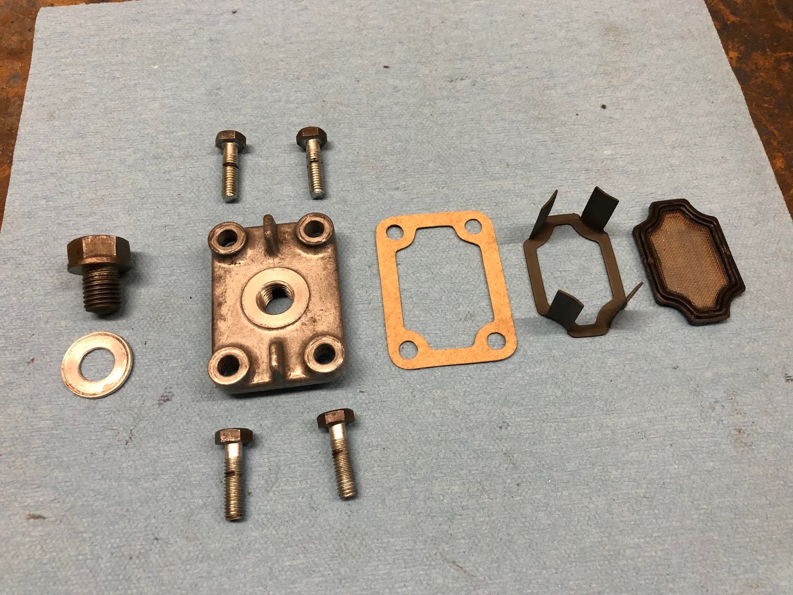
I'll place the housing with the oil filter cavity facing up to make the installation easier.
I'll next drop in the oil screen followed by the oil screen support and then place the gasket for the cover and install the four fasteners that hold on the cover.


Next I move on to the clutch case side cover to install the seal for the kick start shaft and also the small drain plug near the front of the cover.
First I'll install the small bolt and aluminum crush washer that is the seal for the bolt.

These go in the threaded hole on the bottom of the cover towards the front.


Next we'll install the seal for the kick-start shaft following the same approach as was used with the other seals installed earlier.


The next step is to build up the sub assemblies that make up the transmission and I'll start with the shifting fork assembly which includes the parts in the picture below. Some people may not disassemble this assembly, but I always do just to make sure and get all of the crud out of the nooks and crannies.
The first step is to install the shifting fork on each end of the assembly with the small width fork installed from the end with the short stub shaft and the wider shift fork installed from the end with the plate that has five holes.
To install the shift fork slide it over the appropriate end until the threaded hole is over the slot on the shift drum that runs around most of the diameter of the shift drum.

Next place the washer with the locking tabs over the threaded hole making sure the larger tab is engaged with the straight edge of the raised boss of the threaded hole and then install the special bolt and tighten.


With the bolt tightened, fold up the tabs on the washer against the flats of the bolt head to lock it in place.

Now repeat the same steps to install the other shift fork on the other end of the shift drum as shown below.

The next step is to install the headed pins and the retainer plate on the end of the shift drum.
If you are missing any of the pins here are their dimension in inches.
The head on all of the pins is .194 inches in diameter and .106 inches long.
The length of the straight section of the four longer pins is .475 inches long
The length of the straight section of the one short pin is .100 inches long
The diameter of the straight section of both the short and long pins is .055 inches in diameter
With the five holes on the plate at the end of the shift drum four are deep and one is shallow. When the pins are installed the head of the pin should be setting on the plate, so if you insert the long pin in the shallow hole it will protrude out which is incorrect as shown in the picture below.

Install the short pin in the shallow hole and then proceed to install the remaining four long pins as shown below.

The next step is to install the plate and screw that retain the pins.

I apply some blue Loctite to the screw to help make sure the plate won't come loose.

The last step for this assembly is to install the copper component that provides a ground to the neutral light.
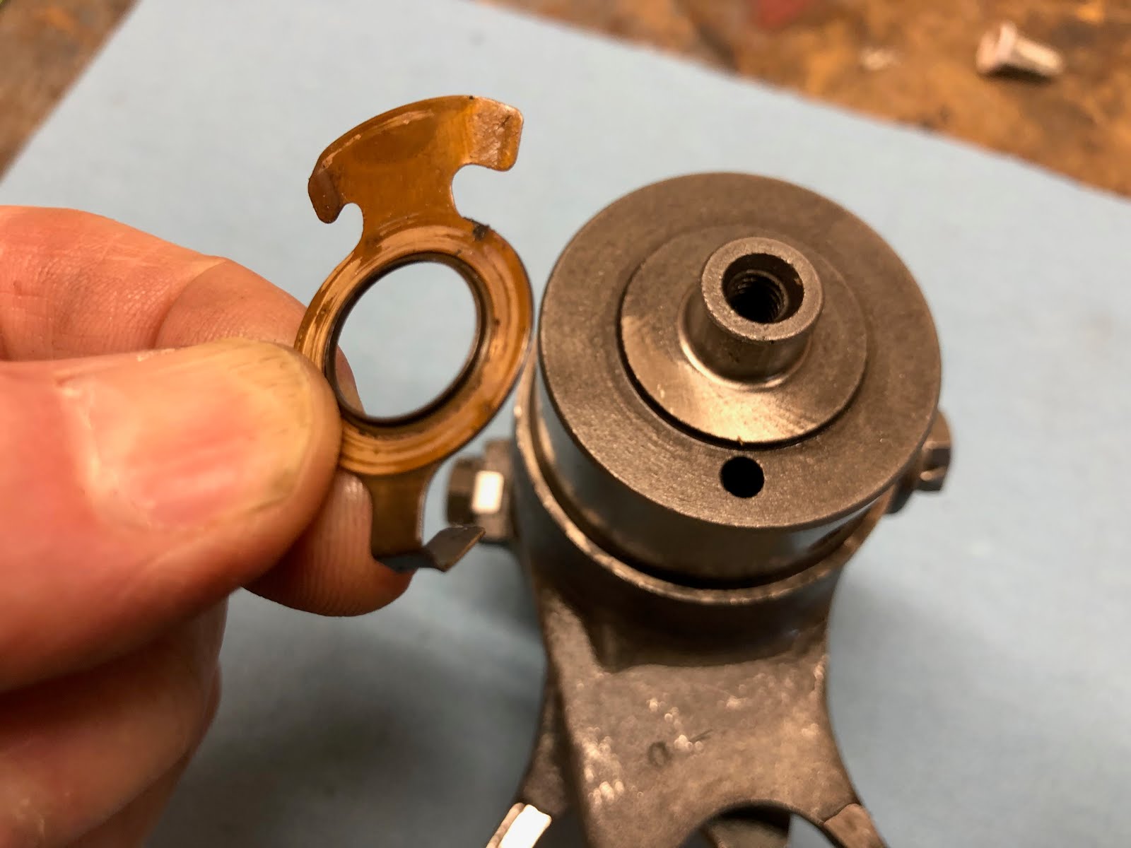
To install this component it is slipped over the small shaft on the end of the shift drum while aligning the hooked end with the small hole on the same end of the shift drum.
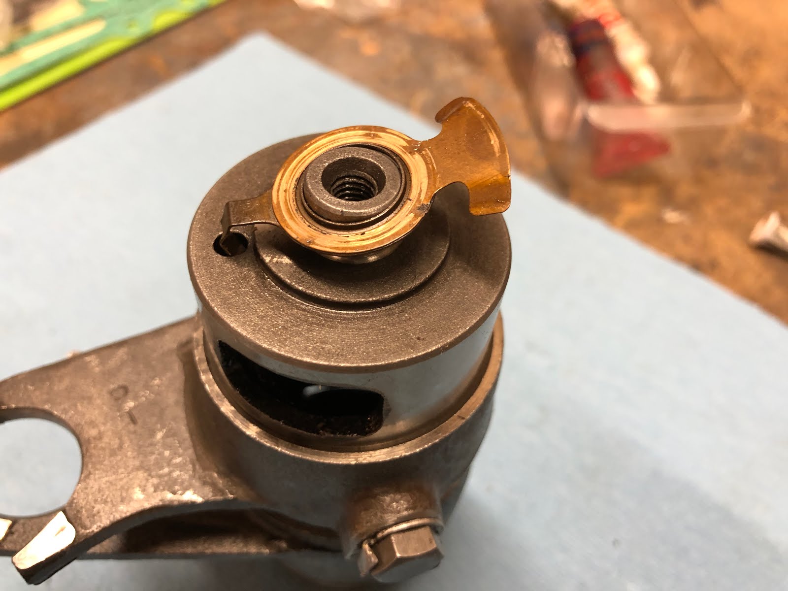
And then gently work the hook down into the hole until the copper component is seated at the base of the shaft as shown below and then this assembly is complete. While I didn't do it hear, this would have been a good time to clean any oxide off the copper component to help ensure you always will have a good ground for your neutral light.
The next step is to assemble the two gear and shaft assemblies that make up the transmission.
Here are the components that make up the first assembly that contains the shaft with the interface that will ultimately accept the chain drive sprocket.

These components assemble in a straight forward manner with the intermediate slid down the shaft with the square dogs mating with the square dogs on the gear that is already on the shaft assembly.

Next the remaining gear is slipped down on the shaft facing the pins on the gear that was just installed. This gear is symmetric and can be installed either way.


Lastly the thrust washer is slipped over the end of the shaft.


Here are the components that make up the second shaft assembly.
This is assembled in the same manner as the previous assembly with the square dog end of the intermediate gear facing the square dogs on the gear that is part of the shaft assembly.


The last gear to be installed is not symmetric and must be installed with the side that has bottomed holes facing the pins on the gear that was just installed.

The last step is to install the thrust washer on the end of the shaft. You can add a little assembly lube to one side of the thrust washer to help it stick to the last gear that was installed as the washer will be facing down and potentially come off when this assembly is finally installed in the engine housing.

The next step is to assemble the two shaft assemblies to the shift fork assembly as shown in the picture below.
The two shaft assemblies are rotated towards each other while remaining engaged to the shift forks as shown below (the one lower gear at the end of the shaft slipped downbeat was moved back to its correct position when it was installed into the engine housing).

The collection of assemblies are then installed into the left center engine housing as shown below.

The next step is to install the components that make up the kick starter assembly.

The first step in building up this assembly is to install the pawl into the pocket as shown below and then spring that actuates the pawl.

The next step is to install the large spring on the assembly
The next step is to install this assembly into the left center engine case so the the tang on the large spring engages the slot in the housing as shown below.


The next stem is to install the plate with the positioning pin down over the kick starter shaft and then you will have to rotate the shaft assembly that was just installed counterclockwise slightly so that the pin in the plate can engage the hole in the housing and be set down in its final position as shown below.


Next one of the two thrust washers is installed down over the lick starter shaft

This is followed by the installation of the gear and then the last thrust washer


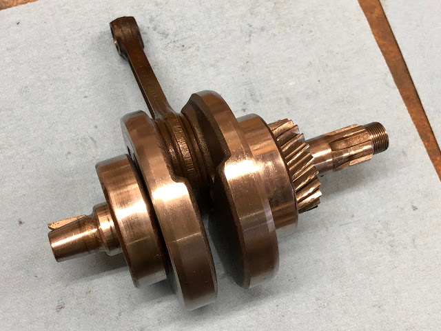
The next step is to install the crank assembly.

The crank drops into the center left engine housing as shown. You might apply a little oil to the lip of the seal that the crank will be passing through to help it more easily slip over the shaft feature the seal will be running on.

The next step is to install the gasket that goes between the two housings and then install the right side center housing.
Sometimes a few very light taps of a plastic hammer can help the housing settle down over the guide bushings and the crank. When using a plastic hammer its the light vibration of the taps that help everything seat and you don not want to apply any hard blows that could potentially damage any components.

To install the screws that hold the two cases together you will have to flip what you have already assembled while holding the cases together.
Next install the screws that hold the two cases together and torque to the specified value.

This is a good time to also trim the excess gasket at the interface where the cylinder will seat.
The next step is to install the bolt that retains the shift fork assembly. Depending on how you like to do things this good have been done earlier if desired.

To get the bolt started you may have to push up on the other end of the shift fork assembly.
And then to tighten down on the bolt the engine may have to come off the wood stand so that a large screw driver can be installed into the screw on the shift fork assembly that holds the pin retainer plate as shown below.
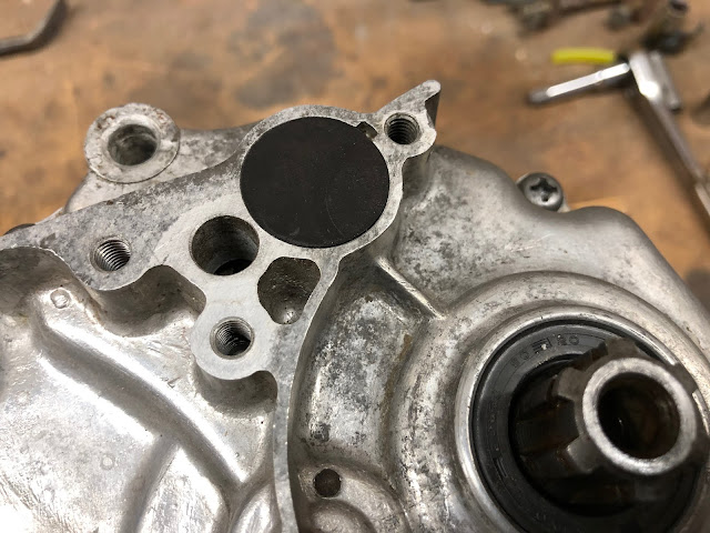
The last step is to install the rubber plug that covers the bolt that was just installed and it is simply placed over the hole and tapped into place.


The next step is to assemble and install the components that make up the gear shift shaft and the shift drum stopper.

The first step is to install the small spring on the arm that interfaces with the shift drum.
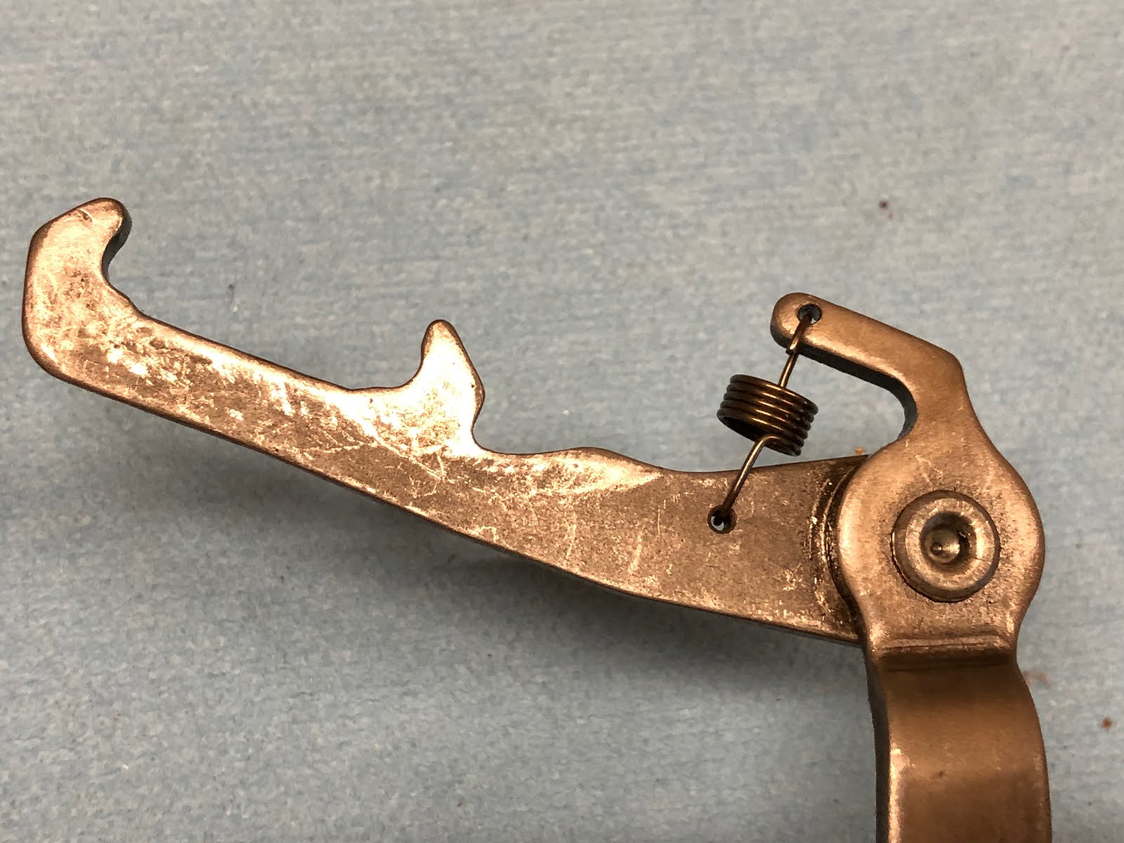
Next the arm assembly is slid down on the gear shift shaft and secured with a retaining ring as shown in the following pictures.


The next step is to install the large spring as shown in the photo below.

Before the gear shift shaft assembly can be installed in the engine the thrust washer needs to be placed over the hole the shaft will be installed into.

Next the gear shift shaft assembly is installed into the hole and slide down until it rests on the housing and then the arm is engaged in the slot with the pins on the shift drum as shown in the pictures below.
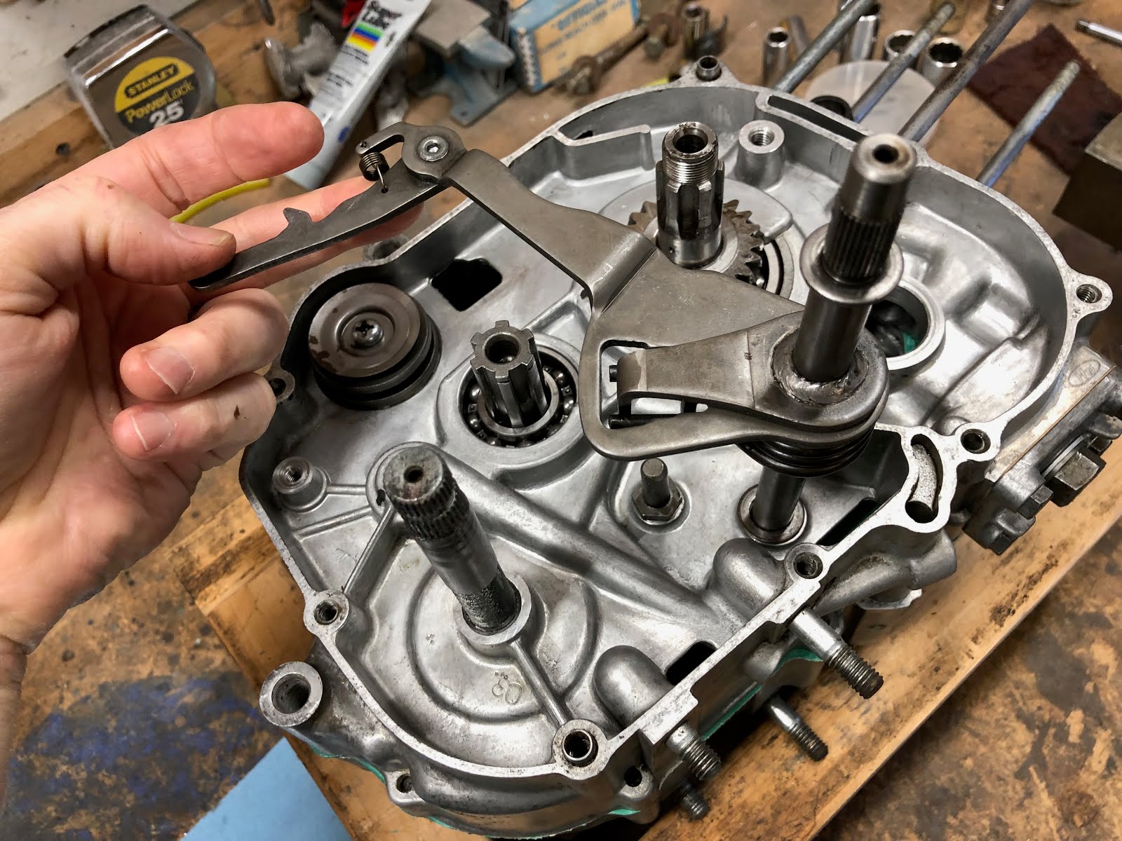

To install the shift drum stopper the spring is attached to the stopper and then stopper is placed in position and the special bolt is installed using blue Loctite as shown in the pictures below. The shift drum stopper ends up ridding on the head of the pins in the shift drum.


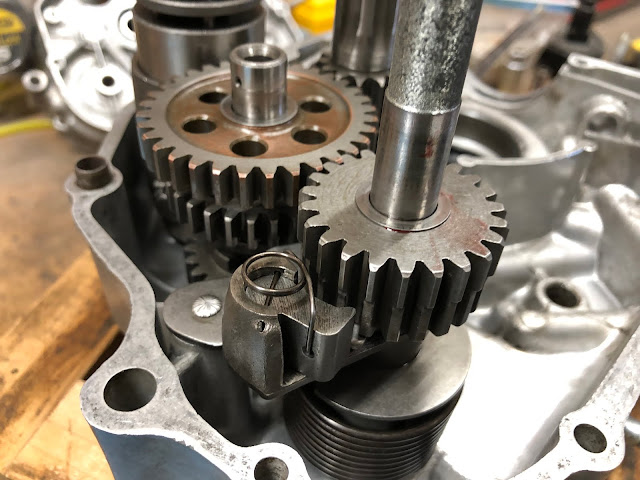
The next step is to install the push rod lifters followed by the cam shaft and timing gear assembly.
The push rod lifters could have been installed earlier when the two center housings were apart, but I chose to wait until now so I wouldn't have to worry about the lifters dropping out of the bores they are installed into while I was handling the engine. It is a little awkward at this step in the process but very doable.
To install the lifters, I will fist add a little assembly lube and the using a magnet I lower each lifter through the opening for the cam shaft and then install one in each of the two bores as shown in the pictures below making sure they are fully seated so they won't interfere with the camshaft when it is installed.


The next step is to install the timing gear to the camshaft. The end of the camshaft that accepts the timing gear has a pin to clock the timing gear to the camshaft. The timing gear is secured to the camshaft with a bolt and washer and its a good idea to add a little blue Loctite to the threads of the bolt.

The next step is to install the camshaft assembly and I'll first apply a little assembly lube to the cam lobes and journals on the camshaft.

When installing the camshaft assembly you have to make sure of two things so the camshaft is installed correctly. The first is to make sure the small pin on the end of the camshaft that drives the oil pump is aligned so that it will pick of the flat drive feature on the oil pump while at the same time you also get the alignment mark on the camshaft timing gear (an "O" stamped between two teeth on the gear)
 aligned with the timing mark on the crank shaft timing gear.
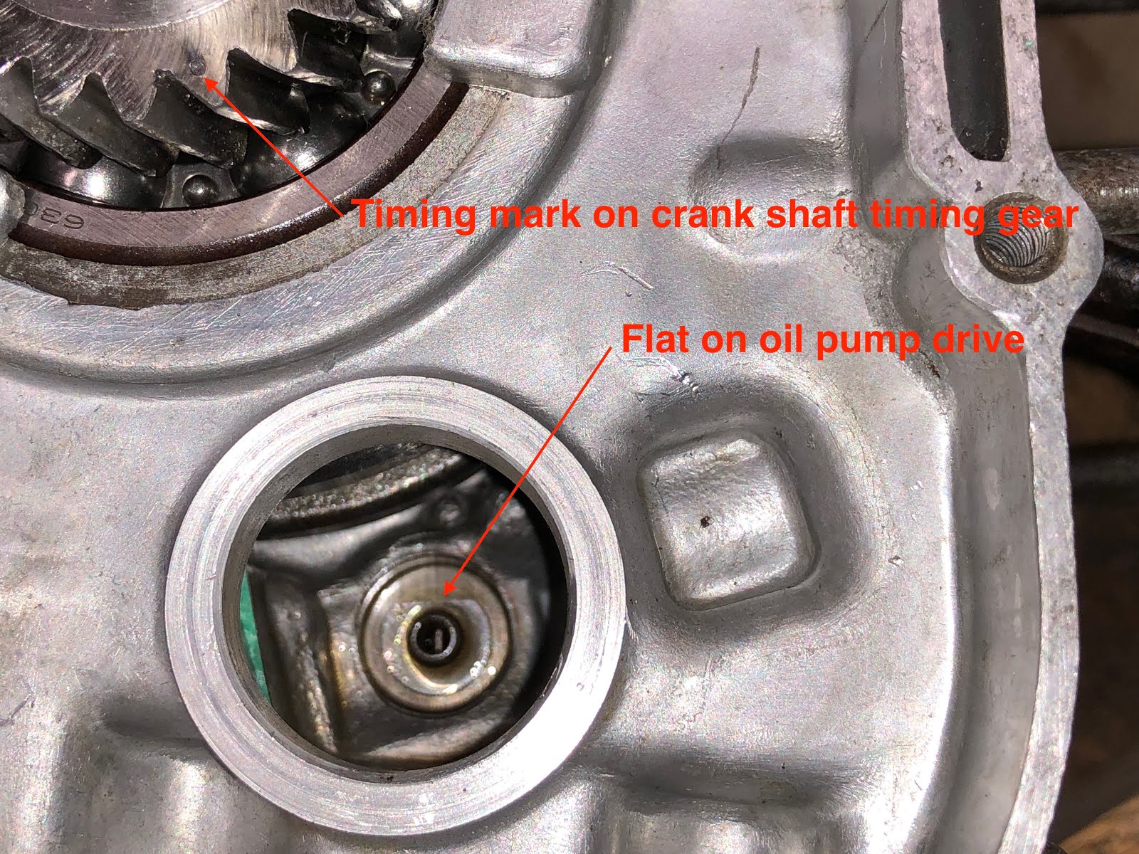
So taking all of the alignment that needs to be done, install the camshaft assembly.

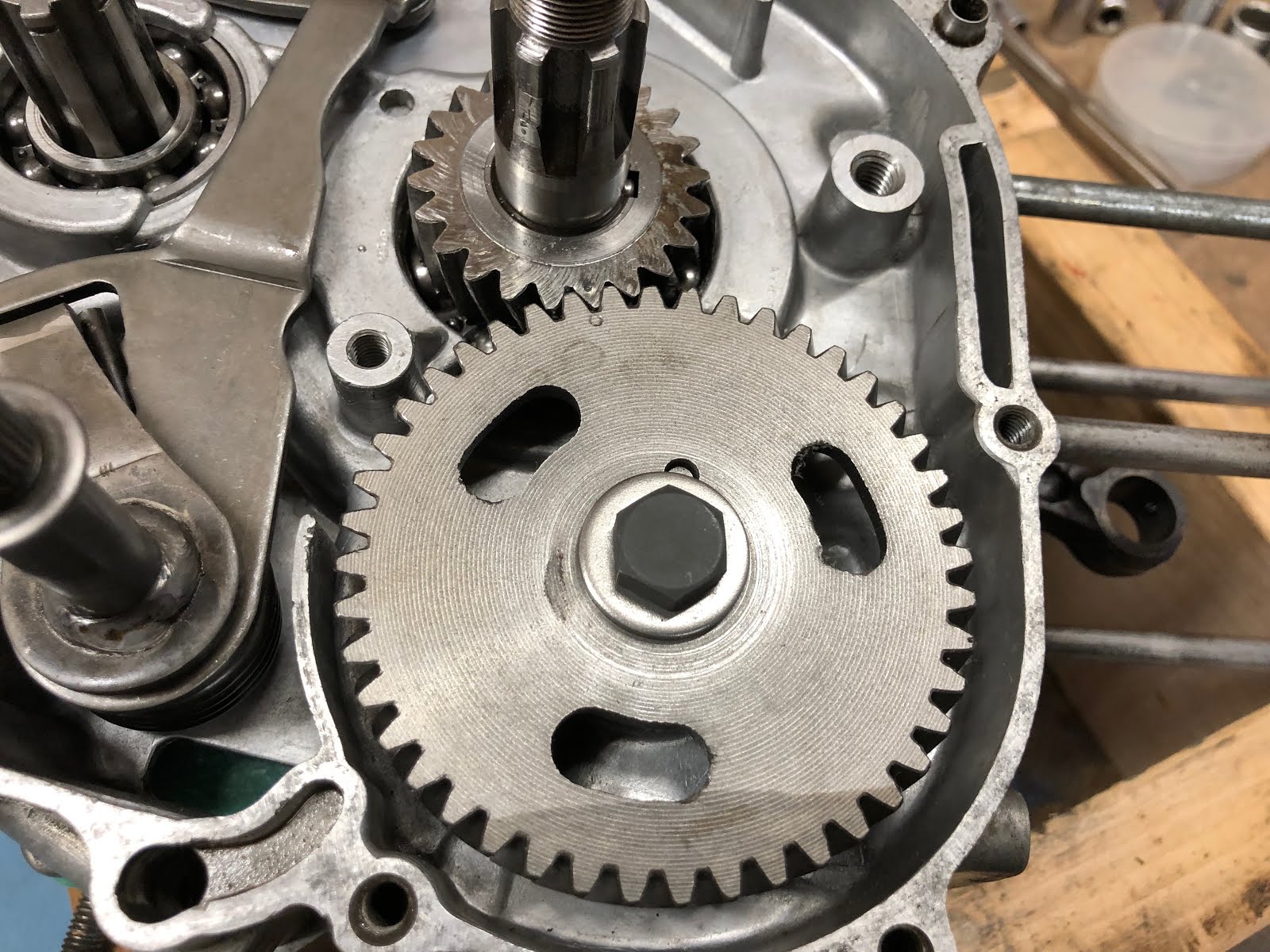
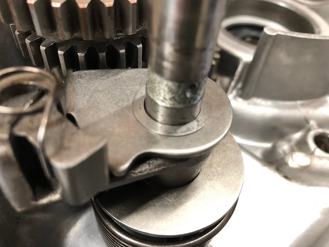
Here is a close up of the two alignment marks on the timing gear after they are installed and this position is also top dead center (TDC).
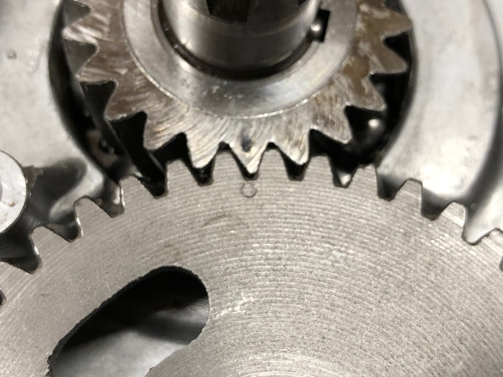
As a side note, when I was initially putting this engine back together I noticed that the timing gear on the crank assembly no longer had a timing mark for whatever reason, so initially I thought I was going to have issues getting the timing gears installed correctly. I then remembered that I had taken photos as I had disassembled the engine and went to the photo below where I was able to identify the tooth on the crank timing gear that would align with the timing mark on the camshaft timing gear. With the picture I was able to look at the stains and other markings on the crank timing gear and go back and identify the appropriate tooth and then I used a center punch to make a new small timing mark.

The next step is to install the drive gear shown in the picture below. This step is pretty simple and it just involves placing the drive gear on the shaft and then install the retaining ring that holds it in place.

The next step is to install the small assembly that directs oil to the timing and drive gear interfaces.

On the one end of the assembly with the banjo fitting there are two aluminum washers that need to be installed. The first goes between the banjo fitting and the housing.
Then position the assembly as shown below.
Next place the second aluminum washer on the banjo fitting and install the hollow bolt taking care not to over torque and shear the bolt.
And the last step is to install the screw at the other end of the assembly and then this step is complete.

The next step is to install the clutch pack assembly. I am not going tp detail how to assemble a CT200 clutch pack assembly here, but I did do a detailed post on how to build up a CT90 clutch pack assembly which is almost identical. Here is the link to the CT90 clutch pack assembly post. I will include the photo below of how the clutch disks and plates are arranged in a CT200 clutch pack to go along with the information provided in the CT90 clutch pack link to help you make sure that you get your CT200 clutch pack assembled correctly.
Here are the clutch pack and associated components from our CT200 that we will install next.
The first step is to install the bushing over the shaft of the crank.
The next step is to install the clutch pack assembly onto the crank shaft and get it engaged with the drive gear.


The next step is to drop in the lock washer and make sure the inner tabs are engaged with the slots/splines of the clutch pack assembly.
Next install the nut that will retain the clutch pack and use a tool to hold the clutch pack (not shown) and a special tool to torque down the nut with a torque wrench.

I also now sell the clutch holding tool in the picture below that I designed and that can also be used to loosen the headset nuts on most Honda CT90's and CT200's. Here is a link to the post I did that includes a link to where I sell the tool on eBay.
With the nut torqued down fold up one of the tabs on the lock washer into the nearest slots on the nut like what is shown in about the 2:30 position in the picture below..
Next install the stamped sheet metal divider into the center of the clutch pack opening.
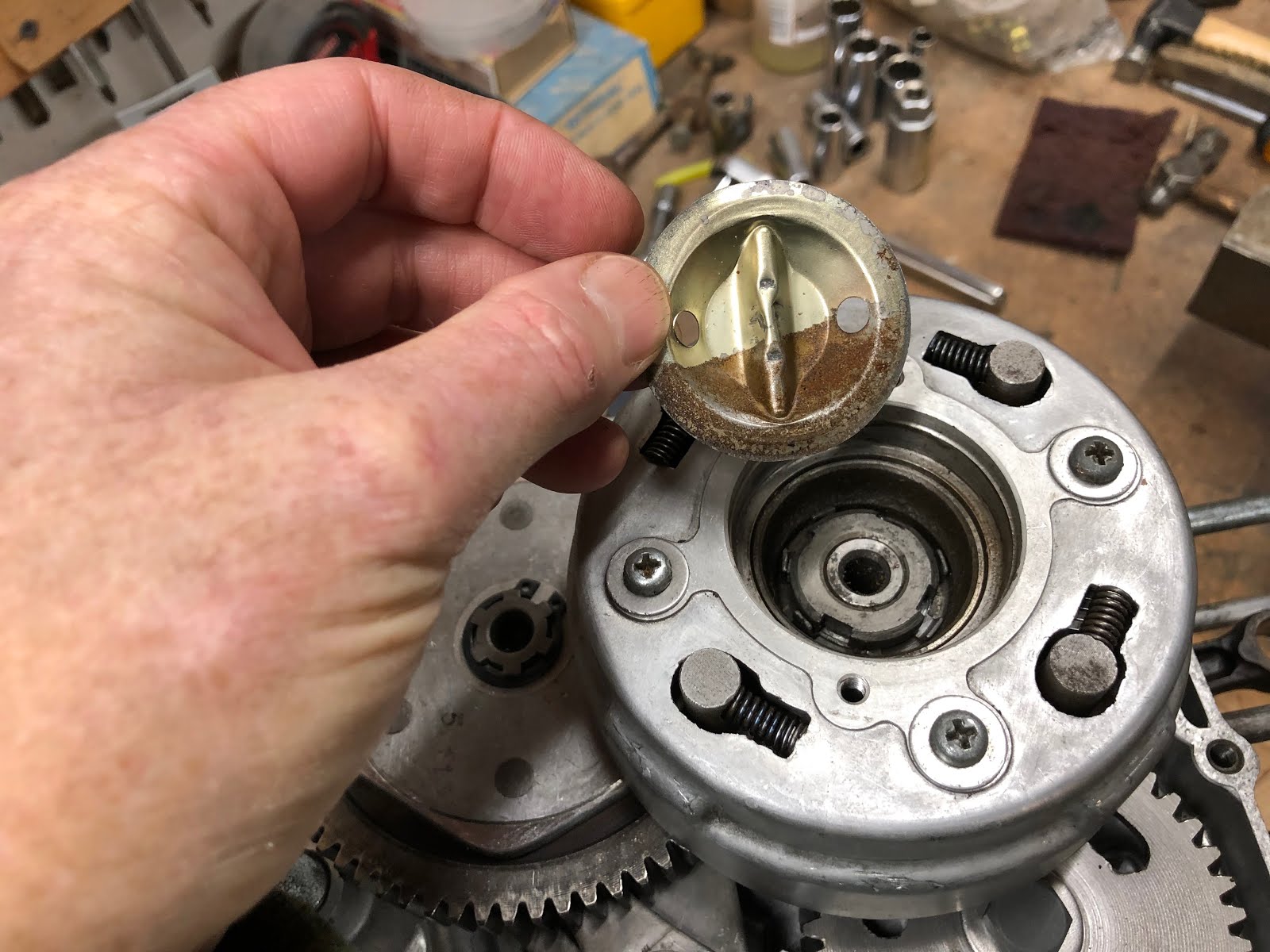

The next step is to install the cover on the clutch pack assembly. The cover has an o-ring that has an ID of 1.90 inches and a .060 diameter cross section which is first installed in a groove on the cover.

Next install the cover using the two countersunk head screws.
With the clutch pack installed which now gives us a way of holding the crank we'll flip the engine over and install the remaining components on the left side of the engine.

The first thing we will install is the alternator stator assembly.

The alternator stator is installed by lining up the wire bundle rubber grommet with the opening in the housing and then setting the stator in place lining up the three appropriate holes in the stator with the three threaded holes in the housing and then install and torque down the mounting screws.


The next step is to install the components that make up the other half of the neutral switch that are shown in the picture below. The neutral switch is really just the copper tab on the shift drum and this neutral conductor encased in a black plastic. When the copper tab on the shift drum comes in contact with the nub at the end of this component it completes the ground path for the neutral light.
The first step is to install the conductor in its hole in the housing making sure the o-ring is installed on the end of the conductor. The straight edge on the rim of the conductor should face the thread hole for the screw that will lock down the conductor retainer.

Then install the retainer and screw.
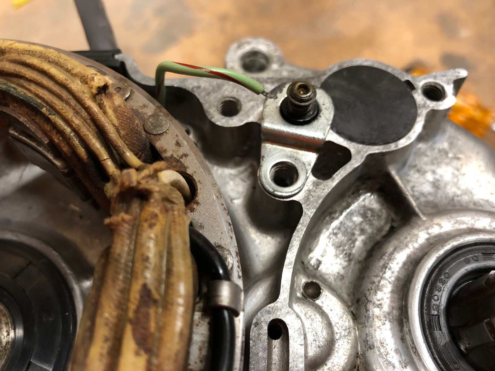
To attach the wire from the neutral light the conductor has a spring loaded washer at the top end which is depressed and then the end of the wire is inserted in the through hole at the top end of the conductor. When you release the washer it will hold the wire in place.

The next step is to install the alternator rotor and the spark advancer. I have a post at the link here on how to assemble a CT200 spark advancer.
The first step is to install the alternator rotor by lining up the keyway slot in the rotor with the key on the crank shaft and then install the rotor.
Next line up the pin in the base of the spark advancer with the keyway on the top of the alternator rotor and set in place.


Next install the washer and bolt that retains the spark advancer and alternator rotor and torque to the appropriate value. To torque the bolt you will most likely need to remove the engine from the wood block and use a suitable retaining tool on the clutch pack assembly. Also, if you are so inclined you may want to add a little blue Loctite to the threads of this bolt before installation.


The next step is to install the cover for this portion of the engine.

First install the gasket which is then followed by the cover and screws.


The next step is to install the points and condenser plate assembly.

To install this assembly simply set it in place as shown in the pictures below making sure the wire that will go to the points is not trapped underneath.

Next install the two screws that retain the assembly, but leave them loose enough so the plate can still be rotated by hand.
To attach the wire for the points, first depress the spring loaded wire retainer as shown in the picture below so that there is an opening for the wire. Insert the bare end of the wire and release.

The installation is now complete and we will come back later after the engine is fully assembled to adjust the points and set the timing.
The next step is to install the drive sprocket.
First slip the drive sprocket on the output shaft.


Next slide the retainer plate down over the splines of the output shaft until it is in line with the groove in the output shaft and then rotate the retainer plate in the groove until the holes in the plate align with the threaded holes in the drive sprocket as shown below.

Lastly install the two short bolts that secure the drive sprocket to the retainer plate.
With that complete we will flip the engine over in the wood block so that we can complete the assembly of the right side of the engine.
The next step is to assemble the components that actuate the clutch pack when you move the gear shift pedal.
The first component to install is the bearing that goes in the bore on the end of the clutch pack.
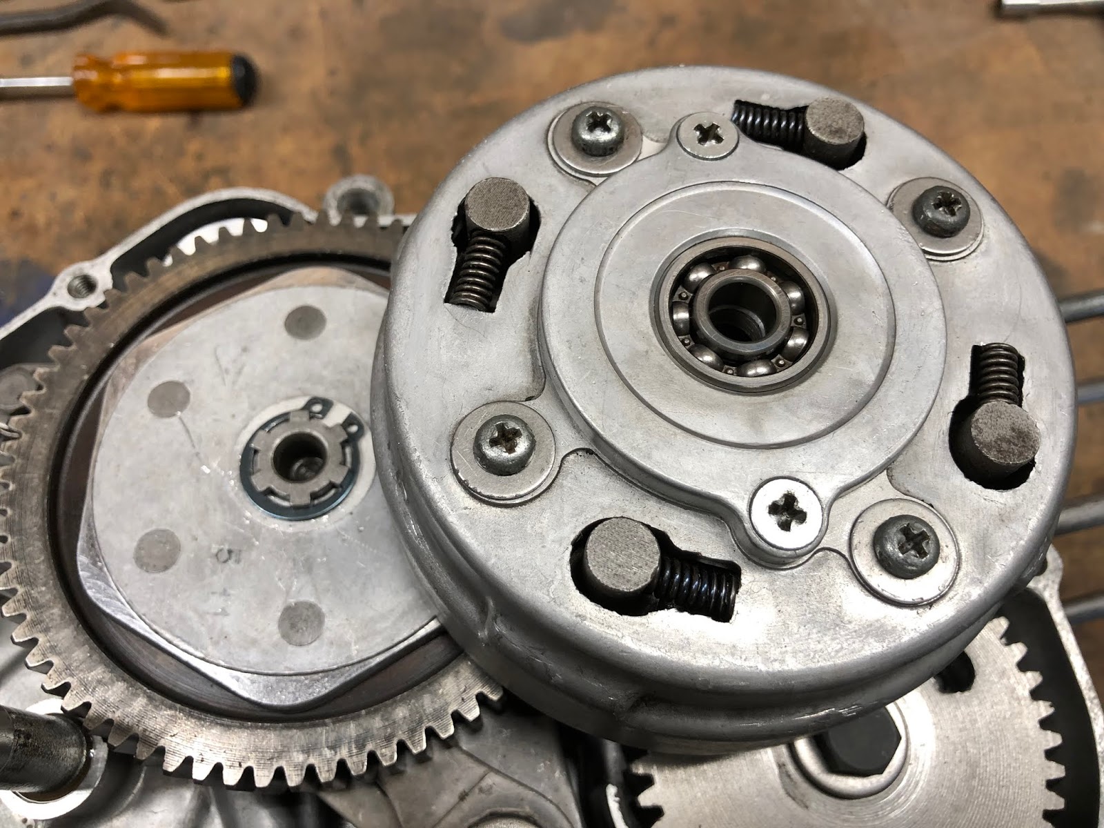
That is followed by the ball-ramp assembly that slips into the inside diameter of the bearing we just installed.
Next we will install the arm that slips on the gear shift shaft and mates into the notch on the ball-ramp assembly we just installed. The important detail with this step is to make sure the arm is pointing at the center of the clutch pack when it is installed.
The next step is to slip the thrust washer over the end of the gear shift shaft so it rests on the arm we just installed.
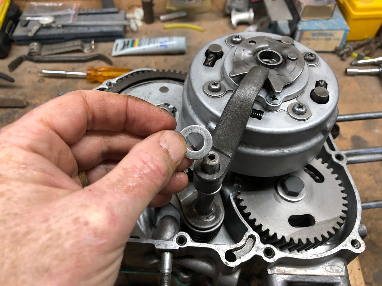
The next step is to install the small spring loaded plunger into the center of the ball-ramp assembly. First assemble the plunger on the spring and then drop it into the center of the ball-ramp assembly.

The last step with installing these components is to place the large diameter spring over the raised rim at the center of the ball-ramp assembly.


We will next install the right side cover, by first installing the appropriate gasket, then the cover and finally the screws that retain the side cover.


The final step to finish off the right side of the engine is to assemble the adjustment mechanism for the clutch to the cover and then install the cover.
First take the threaded shaft and thread it into the stamped ball plate as shown below and then insert into the cover making sure the get the anti-rotation pin in the bottomed hole on the back side of the cover. Its also important to make sure the o-ring is installed on the threaded shaft and this is another seal that didn't come in the gasket kit I purchased so don't lose the one that was on the shaft when you disassemble your engine.


The last step to finish the installation of the adjustment mechanism to the cover is to install the washer and lock nut on the exposed end the the threaded shaft on the outside of the cover.


The next step is to install the clutch cover on the on the case by first installing the appropriate gasket, then the cover, and lastly the screws to retain the cover.

With the cover installed this is a good time to go ahead and do an initial adjustment of the clutch following the instructions in the Honda CT200 maintenance manual.
For the next step we will reposition the engine on the wood block and begin assembling the top end of the engine.

The next step will be to install the rings on the piston and then assemble the piston onto the piston rod.

We'll start with installing the rings on the piston. I'm not going to go into any detail about checking the end gap of the rings, etc. as I have never really bothered to check that on any bike or car piston I have installed over the last 45+ years and have never had a problem. Maybe I'm just lucky, but I think it is more that any automotive or motorcycle manufacture could never afford the time required to do that sort of check in a production environment and the focus is more on holding manufacturing tolerances tight so it won't be an issue.
I am also not going to try and explain in detail how to install each ring as there is a feel to it, so I'll just say that if you haven't done it before take your time and try not to break the compression and scraper rings as they are brittle. If you do end up breaking a ring well welcome to the club and now you with hopefully have the experience that you won't do it again with the next set of rings you have to buy.
On the page I have on video links I do include this link here which is a very nicely done video on how to install piston rings and is a good guide if you have never done it before.
Getting back to assembling this engine, there are there rings that need to be installed.
The top ring is the compression ring.
The next ring down is the oil scraper ring
And the bottom ring is the oil ring and can either be an assembly of three rings or is a single wide ring as is the case for this engine I am building here.
The first ring I will install is the oil ring and you will always want to install the lowest ring first and work up to installing the compression ring last. All rings will be marked something like what is shown in the picture below and the markings always face up towards the top of the piston.

And here is the oil ring installed in the piston.

Next is the oil scraper ring and agin install with the numbers facing up.

And the last ring to be installed in the compression ring agin with the markings facing up.
If you installed all three rings correctly it should look something like the picture below. When you actually go to install the piston in the cylinder you will want to make sure the gaps between all the rings are approximately 120 degrees apart and I prefer to have those gaps on either the left or right side of the piston and not directly on the top or bottom of the piston. Having the gaps staggered helps create a labyrinth seal for any gas that escape through the first gap in the compression ring.
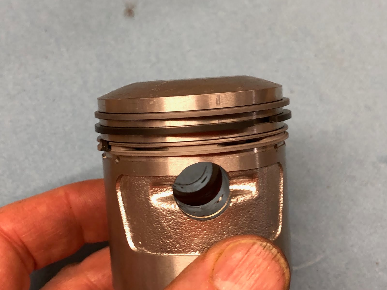
The next step is to install the piston on the piston rod and the important detail here is to make sure the arrow on the top of the piston is pointing down as shown in the picture below.
To install the piston slide it over the end of the piston rod and align the bore for the wrist pin with the bore in the end of the piston rod and then slide the wrist pin through the piston and piston rod until it is centered.

The last step is to install the small clip in each end of the wrist pin bore in the piston to retain the wrist pin.

The next step is to install the cylinder.

First install the gasket over the studs and then start to slide the cylinder down over the studs to the piston.
At this point you want to check and make sure your piston rings are oriented correctly and I will tend to apply assembly lube to the bore, piston and rings.

The end of the cylinder that first engages the piston is chamfered to help with the installation of the rings. I will compress each rings with my finger and work it into the bore one at a time while also hold the piston as I slide the bore down. If you have a large oversize bore there may not be much of a lead in chamfer left, but if you keep at it you'll be able to get the rings compressed and in the cylinder.
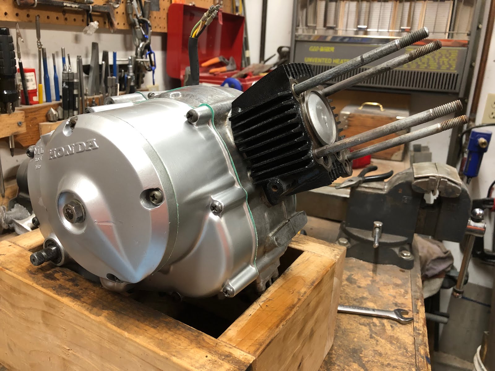
Another way to help hold the piston as you try and slide on the cylinder is to put a 14mm wrench on the head or the bolt for the rotor and spark advancer as shown below.
The next step is to build up the cylinder head.
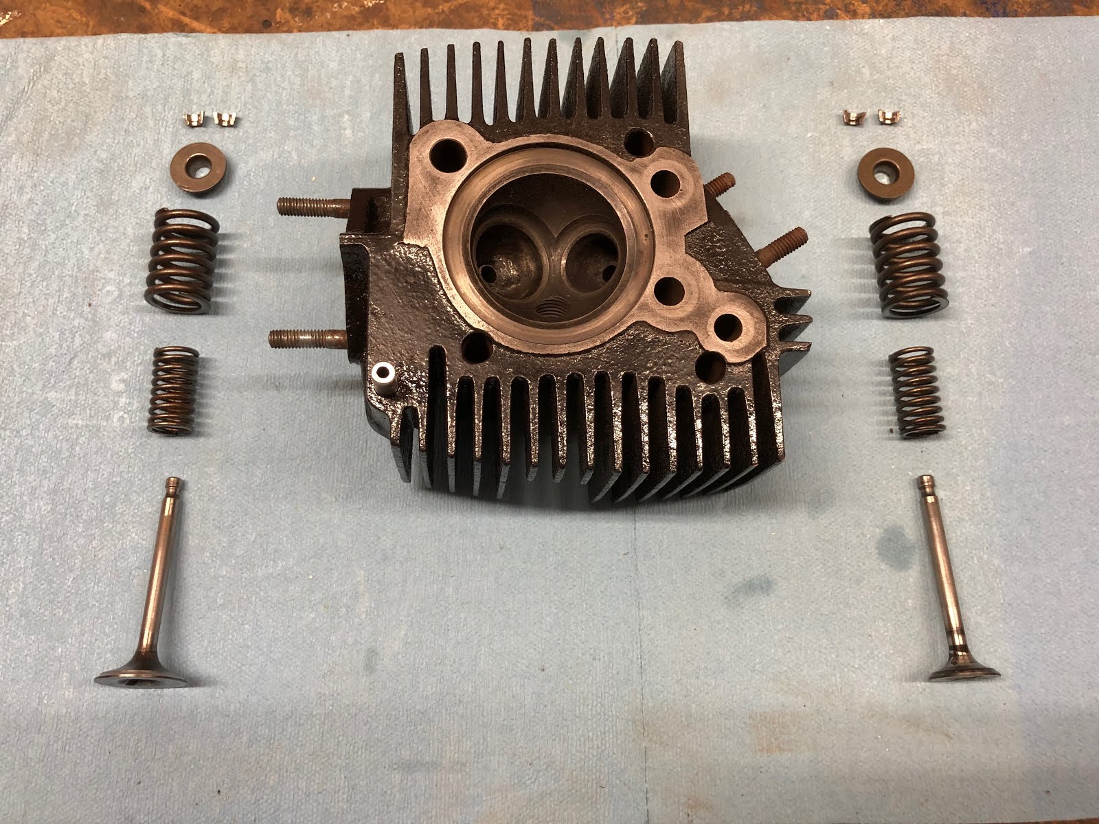
To install the exhaust valve, lubricate the stem and then insert it into the correct hole in the cylinder head. Then on the other end install the inner spring, outer spring and cupped washer that will retain the valve stem retainers.


The next step is to use a valve spring compressor to compress the springs so that the valve stem retainer clips can be installed.
I use a simple tool that I made which utilizes a C Clamp that does the job. I made a post on the method and tool I use here at the following link.


With both retainers installed, remove the spring compressor and the installation of the valve is complete.

Repeat the exact same steps with the intake valve and then the cylinder head assembly will be complete.

The next step will be to install the cylinder head and associated seals on the engine.

for this step it can make things easier if we first re-orient the engine in the wood block so that it is pointing up which will help keep several of the small seals in place during their installation.

Another assembly aid is to apply a very small amount of the assembly lube to each seal as it is a sticky lube and will help hold each seal in place.
Install the three o-rings in there respective positions as shown in the picture below.

Next install the square cross section o-ring in the lower right position as shown below.

The last step before installing the cylinder head is to position the head gasket. I will use small amounts of the assembly lube on the head gasket to help it stick to the cylinder head while it is being lowered into position as shown below.


With the cylinder head now in position holding all of the seals in place the engine can be re-oriented in the wood block for the next step where the rocker arm assembly will be installed.
Here are the components that make up the rocker arm assembly. Its also a good idea at this point to set the adjustment screws on each rocker arm so they are at their loosest setting which will make it easier later on when we go to adjust the valves.

Starting with the longer rocker arm, assemble the spring to the hub of the rocker arm as shown below and then compress the spring and place the rocker arm and spring into the housing with the spring facing the opening that the rocker arm shaft will be inserted through.

Next install the shaft for the rocker arm with a little assembly lube or oil into the bore until it is fully seated.


The next step is to install the short bolt and aluminum washer into the opening that you just installed the rocker arm shaft through and tighten the bolt.

The next step is to follow the same process to install the shorter rocker arm & spring, rocker shaft, and bolt and aluminum washer.


The next step is to install the rocker arm assembly on to the engine.
We first will install the push rods with the long push rod installed into the left hole as you're facing the engine and the shorter push rod being installed in the right hole.


Next install the gasket for the rocker arm assembly as shown below.
Then install the rocker arm assembly over the mounting studs.

Next install the nuts that retains the top end paying attention to make sure that the copper washer and cap nut are installed on the upper left stud as shown in the pictures below. The copper washer acts as an oil seal for the pressurized oil that is being supplied to the cylinder head and rocker arm assembly along this stud.
The final step is to torque these nuts to the value specified in the Honda manual and also following the pattern defined in the manual.

With the basic engine assembled, we will now turn our attention to making some final adjustments to the valves and points and then setting the timing before installing the final covers.
The first thing we will do is adjust the valves and to do this we turn the crank as needed so that the piston is at top dead center on the compression stroke. When you are at top dead center on the compression stroke the timing pointer should be pointing at the mark next to the "T" on the alternator rotor as shown in the picture below and both rocker arms should be slightly loose.

With the engine at top dead center adjust the intake and exhaust valves so there is .002 inches of clearance. Standard practice is to use a feeler gauge to set this gap, but if you are in a pinch and don't have a .002 inch feeler gauge you can screw down each post until it just touches the top if the valve stem and then back it off 1/8 of a turn and that will leave you a gap of about .0024 inches.
Once you have each gap set, tighten the lock nut while holding the adjusting screw/post.

With both valves adjusted, its time to install the two valve access caps.

Install a new o-ring on each cap as shown and the install into threaded openings on the rocker arm assembly.

With the valves adjusted the next step is to adjust the gap on the points assembly.
To Adjust the points to the correct gap we first need to rotate the engine counterclockwise using a 14mm wrench on the head of the bolt holding the spark advancer until the gap on the points are at their widest position.
At this position we use a feeler gauge to check the gap and see if it is in the range of .012 to .016 inches. While any gap in the range is acceptable, I generally shoot for the lower end as it allows more time to saturate the coil at higher RPM's which helps ensure a good strong spark.
This is also a good time to clean the contacts on your points if the are not flat or clean. If you do feel you need to file your points go very easy and remove the least amount of material possible and the clean with contact cleaner so that they are clean and dry when you are down.
The following picture points out the key features related to adjusting your points gap.

So, again use a feel gauge to check the gap as shown below.

If you need to adjust the gap, slightly loosen the two mounting screws as shown below.
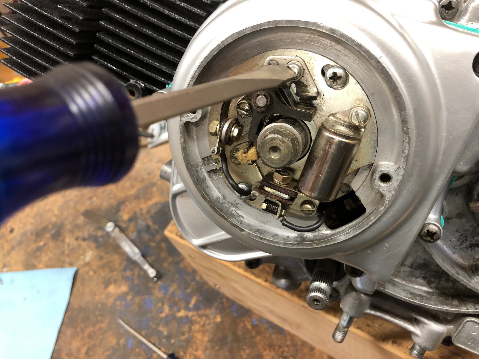

Then turn the small adjuster feature until you have the desired gap and then tighten down the two mounting screws. It is always a good idea to recheck the gap after tightening the mounting screws to see if you still have the desired gap.
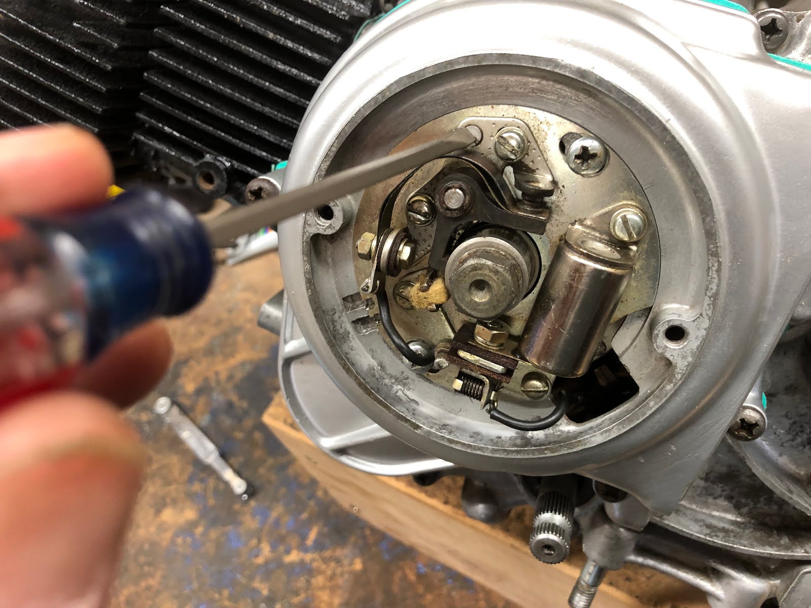
Your points may look slightly different then the points shown in the pictures above as Honda used more then one supplier for points assemblies, but the process should be similar for other brands of points.
This is also a good time to add a very small amount of lubricant to the felt pad where it contacts the cam on the spark advancer. The lubricant helps minimize the wear of the leg of the points that rides on the cam. I use the lube shown in the picture below and I use it very sparingly as I do not want any of the lubricant to ever make its way to the actual points contacts.

The last major step before we can finish the assembly of the engine is to adjust the timing.
At a minimum you will need a static timing light to set your timing and I have a post where I shown how to make a basic static timing light from a almost free Harbor Freight LED light at the link here.
The following picture points out some of the key features involved with adjusting your timing.
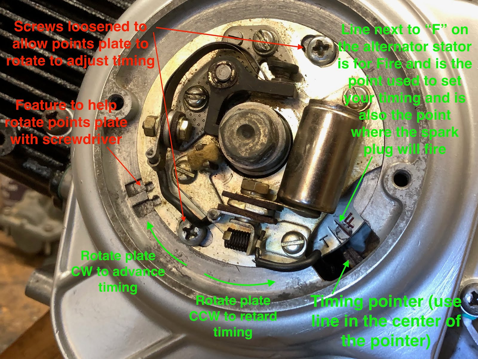
The picture below is how I connect my static timing light. One lead from the light goes to the black wire in the engine harness coming from the points and the other lead from my light goes to a ground on the engine. When the points close the light should come on and when the points open the light should go off.

With the static timing light connected if your timing is set correctly then the light should go off just as the line next to the "F" comes in line with the line on the pointer while rotating counterclockwise on the compression stroke.
If your timing is a little off one way or the other, loosen the two screws that clamp down the points plate so it can rotate as shown below.


Then use a blade screwdriver in the adjusting slot to rotate the points plate either clockwise or counterclockwise to get the timing light to go off just as the line next to the "F" comes in line with the line on the pointer.

Once your timing is finally adjusted correctly it should look like what is shown in the following video.
With the timing complete its time to complete the assembly of the engine by installing the remaining parts shown below.

The access cover has an integral molded rubber gasket and installs with two screws.
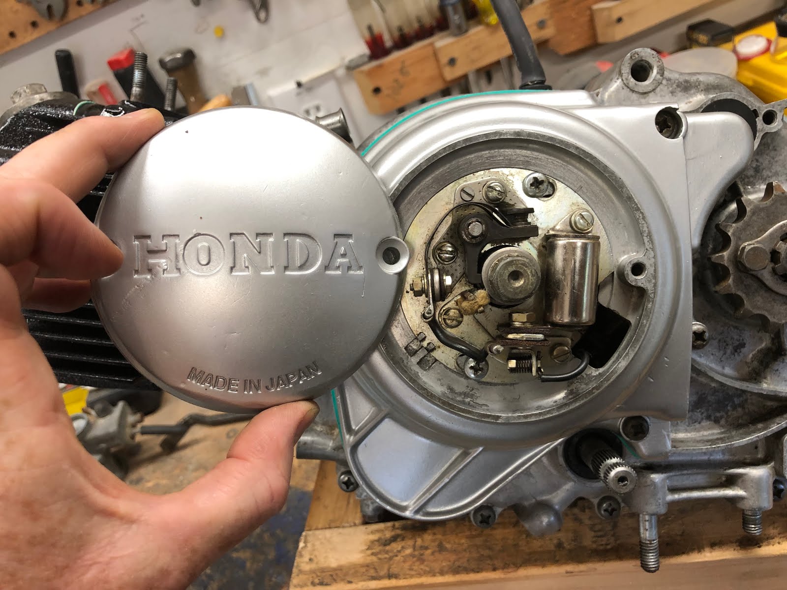

Next install the spark plug.

And lastly install the oil fill cap/dipstick.
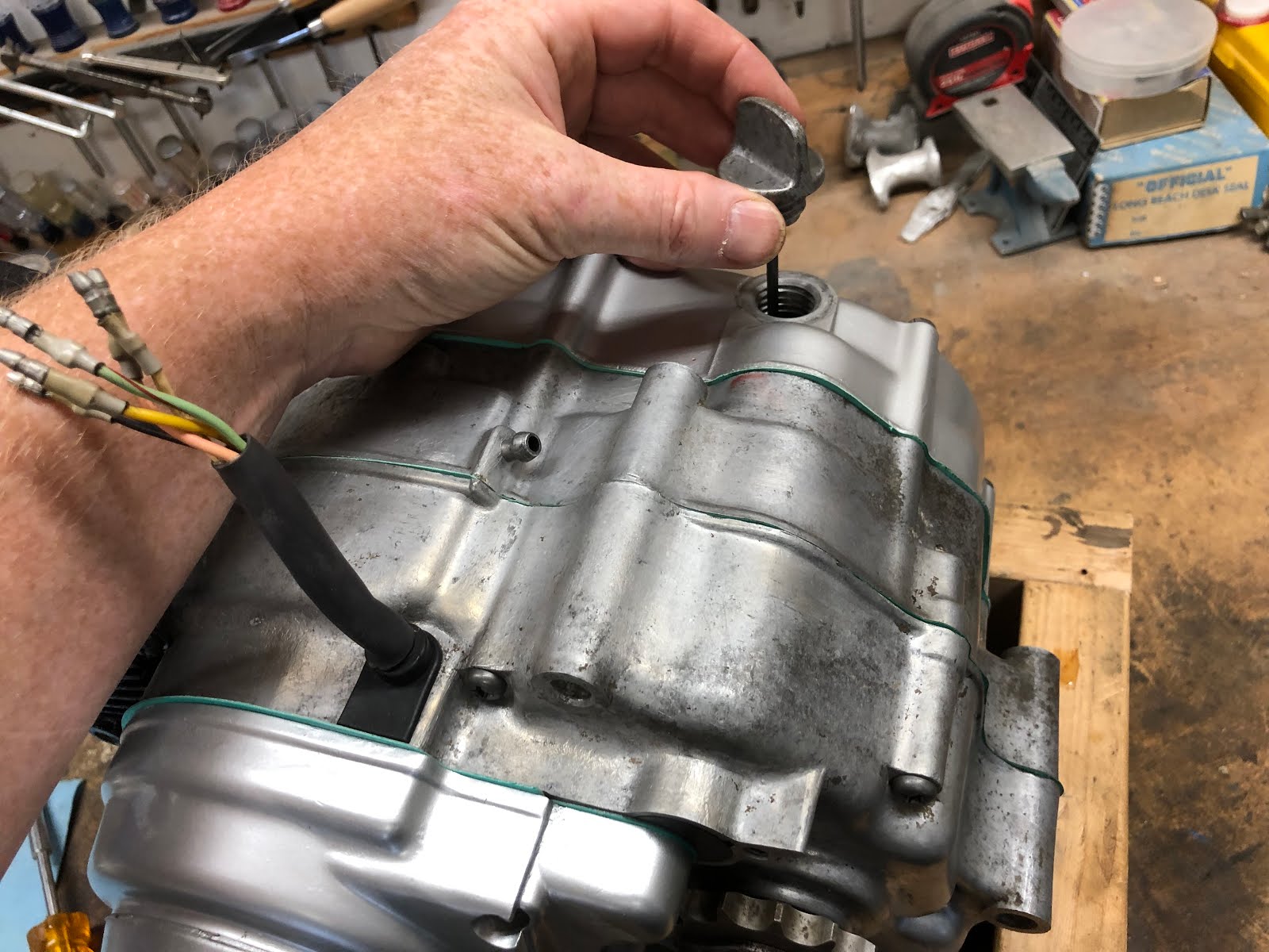
And with that the engine is now complete.

With this engine I will add oil and kick it over a few times to circulate the oil through the engine as it will not be going back on to the CT200 it came off of for some time. I will also add some sort of plug to the opening for the intake manifold and exhaust port to prevent anything from getting into the engine while it is waiting to be reinstalled.
I hope you found this post useful and if you have been hesitating rebuilding your own CT200 engine, don't as it is actually a very simple and straight forward task that I personally also find very enjoyable.
Links to Related Posts:
Honda CT200 Engine Fasteners
Repairing Damaged CT90 Spark Plug Threads Using a Time-Sert Thread Insert
CT90 Clutch Pack Assembly Detail Build-up
Painting Honda CT90 Side Cases
Making a Low Cost Clutch Holding Tool for Your CT90
Building a Basic Timing Light fro a Harbor Freight LED Light
A Simple Valve Spring Compressor
A Simple Way to Check Your Valve Seats
Product Review - Shindy Valve Set 07-002
Helpful Links (Shop Manuals, Wire Diagram, Model Information, etc.)
Link to page with listing of CT90 & CT200 parts available on Amazon
Scanned the articale quickly. Liked what I saw.
ReplyDeleteJust bought a 1965 CT 200; needs work but looks like much of it is there. The last one I had was bought as a basket case back in 1967 for $50.00 (seems cheap today but I started at Penn State that fall and tuition for the year was $300,00). It was 3 yrs old at the most. Just needed some basic engine freshening to make run. Hope this recent one doesn't take much more!!!
Thanks
Mark