Honda CT90 Engine Reassembly
I have one 1971 CT90 where I was going to rebuild the clutch because the kickstarter just wasn't turning over the engine like it used too, and I also had a Big Bore kit from DrATV that I wanted to install. My intent was to just do the top end and rebuild the clutch with new disks, but when I opened up the cases to rebuild the clutch pack I found a slick black slime in the bottom of the case. I didn't like the idea that there could be black slime in the rest of the engine, so I decided to disassemble the entire engine to make sure I cleaned everything out. Since I was tearing everything apart I thought I would document step by step how everything goes back together in this post in case others were interested in knowing what the inner workings of a CT90 engine look like.
Links to Related Posts:
My Honda CT90 Clutch and Headset Nut Tool
Cut Away of a CT90 Engine - CT90 Engine Exposed!
Repairing Damaged CT90 Spark Plug Threads Using a Time-Sert Thread Insert
CT90 Clutch Pack Assembly Detail Build-up
Painting Honda CT90 Side Cases
Making a Low Cost Clutch Holding Tool for Your CT90
The Basic Sequence and Process to Set or Adjust your CT90 Timing
CT90 Sub-Transmission Reassembly
CT90 Spark Advancer Assembly Build-up
Product Review - Shindy Valve Set 07-002
Honda CT90 Engine Fasteners
If you've thought about tearing your own CT90's engine apart, but have avoided it because you thought it might be two difficult, you should really give it a try. The CT90 engine is really a very easy engine to work on and is difficult to screw up when you reassemble it as everything goes together so easily.
Also, if your interested in how the inner components of a CT90 engine actually work, please take a look at a video I made here at this link which shows in detail the inner workings of an operating CT90 engine using a cut-away engine I machined up.
As I outline how I go about reassembling the engine, I may not use the official terminology for what each one of the parts may be called by Honda, but you should be able to get an idea of which physical part I am talking about. There are a number of fasteners that should be properly torqued during the assembly process and while I don't call out those torque values here you can easily look them up at the links I have to Honda manuals on my Helpful Links page.
Here is a shot of the engine at the end of the rebuilding effort.

Before I started reassembling the engine, I took everything apart and cleaned and inspected all the parts, replaced any screws or fasteners that got buggered up during the disassembly process. I also decided to switch all of the fasteners that hold the cases together to socket head screws which I think is well worth the cost as it makes it very easy to disassemble the engine in the future.
Here is a picture of the majority of the parts that go into the engine. The side cases are not shown as I was in the process of cleaning and painting them using the same process I shared in another post I made here on how to paint your ct90 side cases.

One item that helps make the assembly process that much easier is a simple engine stand made from four pieces of wood like the one I use in the picture below.

The dimensions for the stand that I use are that it is 13 inches long, 10 1/8 inches wide, and 5 1/2 inches high. I made mine from a scrap 2 x 6 I had in my shop. Having some sort of stand like this does make the assembly process that much easier.
Before you get started you will also need to have a set of gaskets and seals. For a CT90 with a dual range transmission I have found the Vesrah VG-168 gasket set without seals found here at Amazon to be inexpensive and of good quality. I have also used and been happy with gasket sets from Athena. 4 into 1 also sells NE brand gasket sets that are available with and without shaft seals on Amazon, but it is important to note that neither of these sets come with the gasket for the dual range gearbox cover which can be frustrating to discover at the end of a build. The 4 into 1 NE brand gasket sets cover both push rod and timing chain CT90 engine configurations, and they do point out in the description of the set that the dual range gasket is not included, but you should make sure that you don't need that gasket before ordering either one of those sets. For the shaft seals I have ordered off of both eBay and Amazon and not had any issues with the sets I received which have all been like this set from 4 into 1 on Amazon.
Another detail worth pointing out is that it is always a good idea to apply a little oil or assembly lube to any metal surface that will run against another to help provide some lubrication during the initial start-up of the engine prior to the oil getting circulated. I use Permatex Ultra Slick also available on Amazon.

The first thing I do when I start to put a CT90 engine back together is to do some sub assembly work on each of the two center cases. I'll start with installing the parts that make up the oil pump assembly on the right side case that will ultimately hold the clutch assembly.
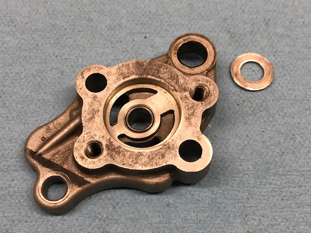
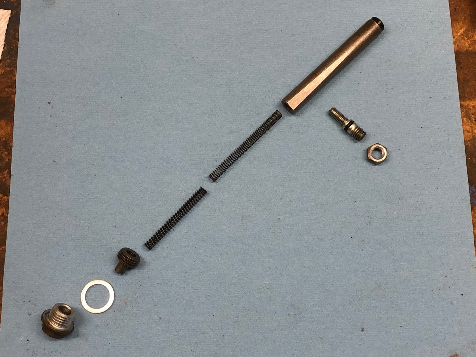
Here are the parts that make up the oil pump assembly:

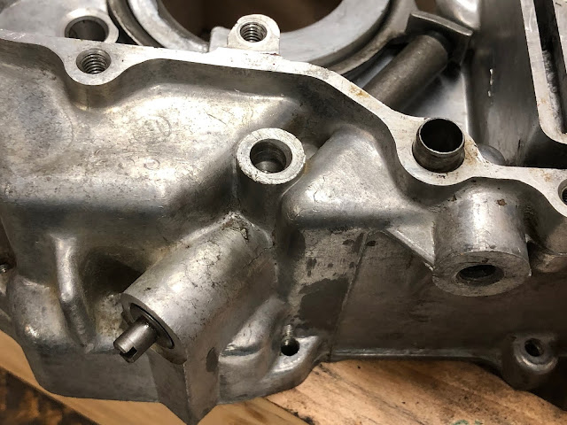
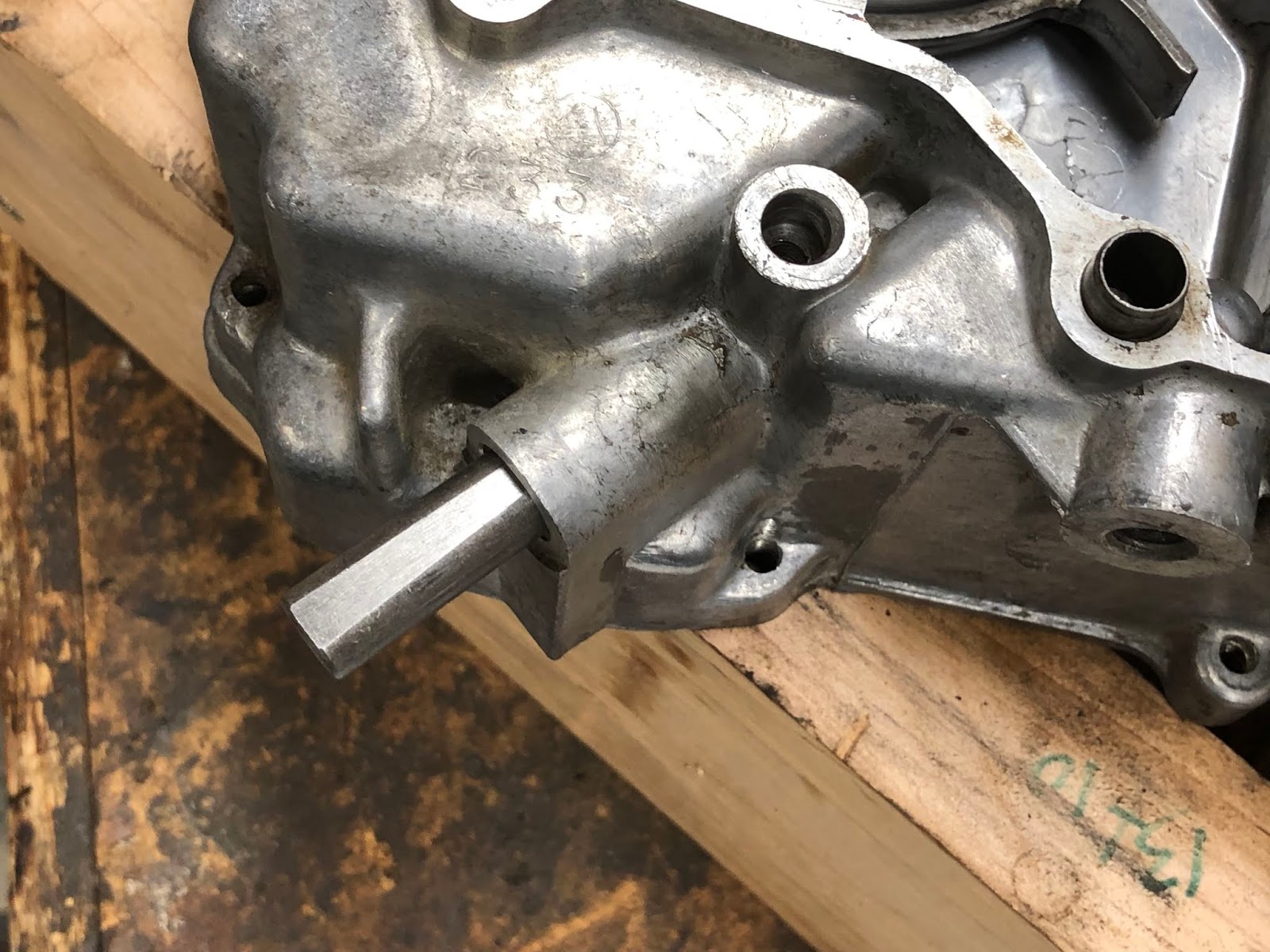
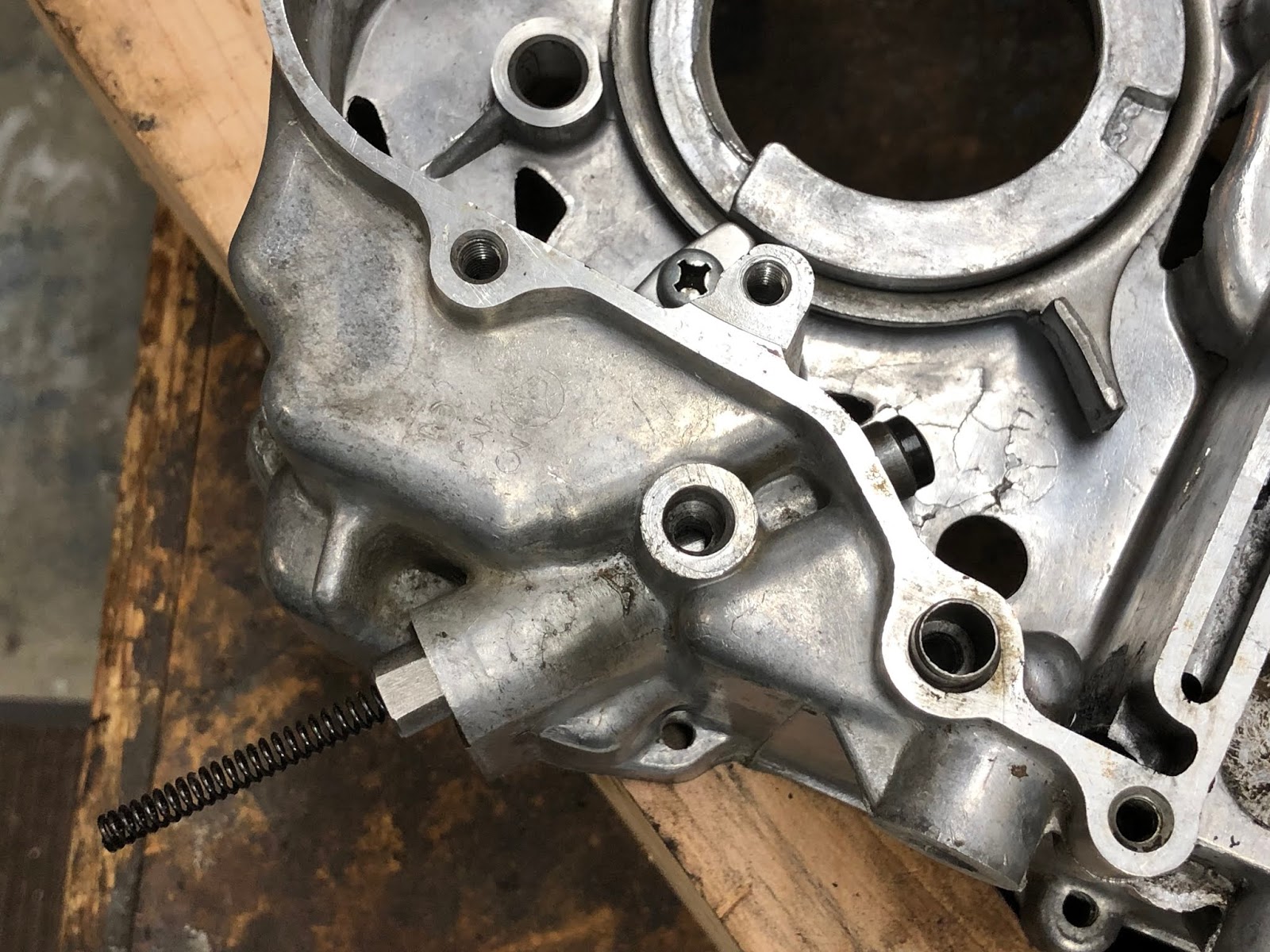
While I won't mention it at each step in the assembly process, its always a good habit to check all the oil passageways while you are assembling each part of the engine to double check that they are free and clear. With the oil pump assembly there is the one hex bolt that has its center drilled out and one hole drilled in the side that I always double check to make sure it is clean and open by shining a flashlight in the side hole and making sure I see light when I look down the hole bored down the center of the bolt like in the picture below.

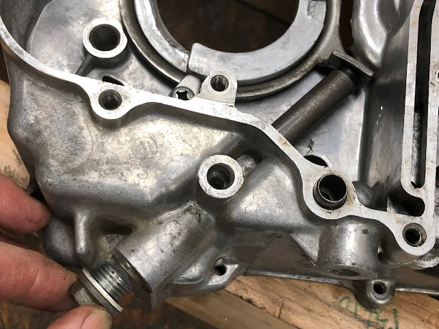
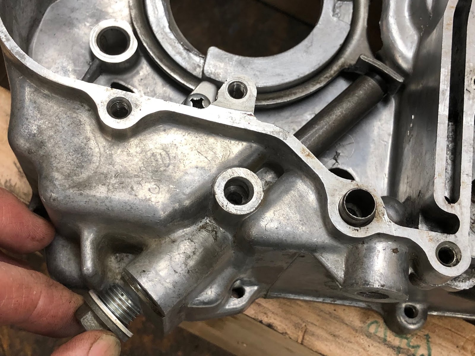
While its not always obvious there is an aluminum crush washer that goes underneath the drilled hex bolt and acts as a seal for the head of the bolt. Most of the time this crush washer is "stuck" to the oil pump housing and not really noticed. It's important not to loose this crush washer, so if it does separate from the housing during cleaning make sure to hang on to it and install it under the bolt during assembly.
Getting back to assembling the CT90's oil pump start with the base gasket.

next set on the oil pump housing.

Then drop in the small shaft that has a flat on one end that will drive the pump.

Then drop in the two components that are the actual oil pump.


Add the next gasket.

Then add the final cover and the fasteners.


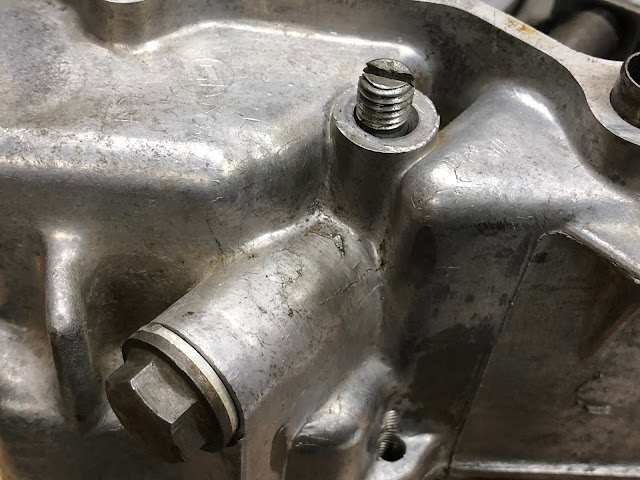
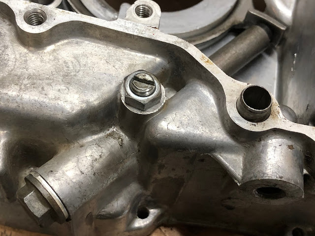
Then tighten the fasteners down being careful not to over torque the hollow bolt and to have also installed the aluminum crush washer if it was loose from the pump housing.

To make sure the oil pump is assemble correctly and not binding, I'll temporarily insert the shaft/gear that drives the pump from the timing chain and rotate the pump like what is shown below.


For the next part of the assembly process I work on installing some components on the left housing. I start by installing the seal that will seal on the shoulder of the drive sprocket.

I'll first set the seat in the bore where it will be installed.

Then I'll use something like a block of wood and gently tap it into place until it is flush with the rim of the bore I am installing it into.

Next I'll work on installing the parts that make up the timing chain tensioning system.

The first step is to set in place the assembly that has the roller that rides on the timing chain and the tab that engages the spring loaded plunger that generates the force that tensions the timing chain.

The ring is captured buy three metal tabs two of which are identical and one that is unique. The unique tab that has a small feature/key is installed at the position near and underneath the roller, with the small key like feature engaged in the mating slot in the housing that will keep it from rotating.

The other two tabs are installed in the remaining positions with the curved edge of the tab facing down so the it will keep the tab from rotating when it is in its final installed position.

The next step is to install the spring and plunger components that provide the force to tension the timing chain. The parts that make up this assembly can vary between different years of CT90 engines, but the one I am installing here is the simplest configuration.

The installation of these components it pretty straight forward and is shown in the series of pictures below.


Here is a picture of the left side case with theses sub assemblies installed. At this point I'll check that the timing chain tensioning ring can rotate against the spring loaded piston.

There are actually a few different configurations of plunger assemblies used in the cam chain tensioning assembly on CT90's. I thought I would include the series of photos below on the plunger assembly from a 1972 CT90 I am currently rebuilding since this is a common configuration on many later CT90's.
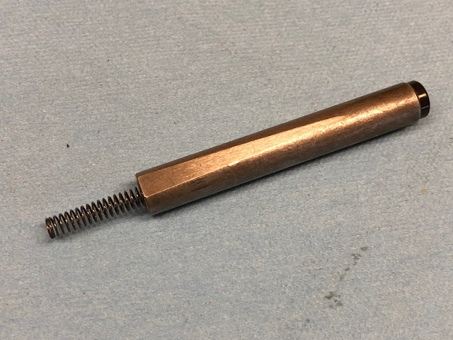
Here are the components associated with the plunger assembly and this has the added feature in that the spring force is adjustable to account for any stretch in the cam chain over time.

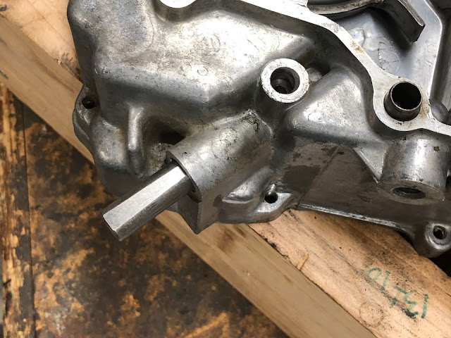
The first step is to insert the softer spring into the bore of the plunger and then insert that assembly into the opening in the housing with the tampered flat on the plunger facing upwards as shown in the pictures below.
Next insert the stiffer spring into the bore of the plunger and then to push the plunger up all the way until it contacts the tab on the tensioning assembly. Then take the threaded plug and use it to compress the stiffer spring while you screw it into the housing as shown in the pictures below.

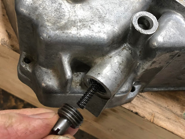
Continue to screw in the threaded adjusting plug until it is in far enough so that the threaded cap and aluminum sealing crush washer can be installed.
The last step is to install the threaded stud and lock nut that is used to lock the plunger down once it has been adjusted. It is important to make sure the o-ring is installed on the stud prior to its installation.


Once you have your CT90 up and running you will need to come back and do an initial adjustment with this cam chain tensioning system. If you go to the following link here and scroll down about a third of the way you will reach a section titled Cam Chain and this has the basic procedure you need to follow to adjust the cam chain tensioner with this type of configuration.
Getting back to assembling the 1971 CT90 engine...
The next step of the process is to build up the sub assemblies that make up the transmission. I'll first build up the shifting fork assembly that includes the parts in the picture below. You might not bother to disassemble these parts if you were rebuilding your CT90's engine, but I did it here because I was really trying to get all the internal parts clean.

The first step is to install the copper sheet metal part that is what actuates your neutral switch.

To install this part you slip it over the short shaft one the one end of the shifting drum and then carefully insert the hooked tab into the hole it mates too.


The next step is to install the two shifting forks onto the drum.

The two shifting forks are slightly different and the one with the smaller fork being installed on the end of the shifting drum with the short shaft and the other with the larger fork being installed from the other end of the shifting drum.
Each of the shifting forks has a hole near the base of the fork that you will install a grooved pin. To install the shifting fork slide it on the correct end of the shifting drum until the hole is lined up with the waves groove that runs around that end of the drum.

Once the hole is lined up with the correct groove drop one of the pins in with the groove facing up. A small magnet is helpful when you are trying to remove these pins.

Once the pin is fully inserted (it will be flush with the top of the hole you are inserting it into) then take one of the small wire spring clips and slide it in through the two small holes on the face of the fork as shown in the picture below to lock the pin in place.

After you complete the installation of the one shifting fork repeat the installation process with the other shifting fork.
The next step is to assemble the gears and shafts that make up the transmission and are shown in the picture below.

These parts are assembled by sliding them on to the shaft in the order shown in the photo above and the end result is shown in the photo below.

One important detail that is not shown in the above picture is that the last gear installed on the smaller shaft assembly has both a solid face and a pocketed face. The pocked face should be installed facing the pins on the gear that was installed first on the smaller shaft.
The next step is to mate the shift fork/drum assembly to the transmission gear shaft assemblies. with the shifting forks engaging the sliding gear of each of the shaft assemblies as shown in the picture below. The smaller shaft assembly was flipped in the picture below so that it would correctly mate with the shift fork/drum assembly.

The washer shown in the above photo is a thrust washer that will be installed on the end of the larger gear shaft that it is next to in a later step.
In the next step of the assembly process we will install the transmission gear assembly we just finished putting together into the left engine housing that we earlier installed the timing chain tensioning assembly into. To prepare for the installation of the transmission gears first take the left engine housing and set it on your wood engine stand with the timing chain tensioning components facing down.
Next fold/rotate the two transmission gear shaft assemblies towards each other while keeping the shifting forks engaged so that you have an assembly like is shown below setting in the palm of your hand.

Next take the assembly that is in your hand and insert the long larger shaft through the ball bearing in the left engine housing and slide down the complete assembly until the short shafts on the end of the smaller gear shaft and shifting drum are seated in their respective bores in the left engine housing as shown in the pictures below.


In order to secure the gear assembly we just installed into the housing we need to install a special bolt and washer into the threaded hole of the shifting drum as shown in the pictures below. You'll need to lift up the housing from the engine stand to install this bolt and I will usually put a drop or two of blue loctite on the threads of the bolt.


With the left engine housing setting back down on our wood engine stand, our next step is to install the crank and main bearing assembly. With the crank assembly in the orientation shown in the picture below lower it down so the main bearing engages the bearing bore in the housing.

If the crank assembly doesn't drop immediately into the bearing bore it is ok to take a plastic mallet and very lightly tap on the shaft or around the crank until finally drops into place.

The next step is to now take the thrust washer I mentioned earlier that goes with the larger shaft of the transmission assembly, and install it on the end of the shaft as shown in the picture below so that it is resting in the end of the large gear on that shaft.


To finish off the engine housing, I install the main gasket. There is a small section of the gasket that goes across the opening for the piston rod that can either be removed now or later.

The next step is to assemble the kick starter shaft and spring and then install that assembly into the right side engine housing.

The spring just slips over the end of the shaft and the shorter hook engages a mating feature on the arm on the shaft as shown in the picture below.

That assembly is then installed from the inside of the right engine housing through the appropriate hole as shown in the picture below.

The kickstarter shaft assembly is slid all the way into the housing and the closed loop portion of the spring is mated into the cast feature of the housing as shown in the picture below.

The next step is to engage the remaining hooked end of the spring into the opening in the casting as shown in the picture below.

The last step is to pull the shaft back out just far enough so the the arm the the short hook is mated too can be rotated clockwise (which winds up the spring) until it is past the blocky stop feature of the housing and then the shaft assembly is pushed all the way back into the housing until it is seated.

I made the following short video to show the basic function of the kickstarter shaft and gear.
With both of the engine cases complete to this point its time to assemble them together.

With the left engine case setting in the wood assembly tool, lower the right case down over the various shafts until the to housings are together.

With the two housings together, the next step is to install the screws that will finalize the assembly. I am using socket head screws and I always apply an anti-seize compound when installing steel screws in an aluminum housing. I strongly recommend the use of socket head screws as it makes any disassembly in the future much easier.

Then torque down the screws to the appropriate torque value.

The next step is to install the shift drum stopper pins and plate.

The first step is to simply insert one of the pins in each of the four holes in the end of the shifting drum.

With all of the pins installed one of them will be proud or sticking out slightly and that is what is used to clock the plate to the drum.


The next step is to install the screw that holds the plate to the drum and I will always use "blue" loctite on this screw to help prevent it from coming loose.

The next step is to install the shifting linkage and shift drum stopper components.

To begin the process slide the shaft through the linkage arm and then insert the shaft through the appropriate hole in the housing as shown in the picture below

Next, without the shaft fully inserted into the housing lower the linkage arm all the way down so that the two legs of the spring engage the post in the housing and then with your finger rotate counterclockwise the smaller spring loaded arm that will engage with the groove and pins of the shifter drum.

Once clear of the shifter drum lower the arm the remaining distance and then let go of the smaller spring loaded arm so that it engages the groove in the shifter drum like is shown in the picture below.

The next step is to slide the shaft the remaining distance into the housing until the notches on the bent arm on the shaft engages the two legs of the spring that was part of the linkage assembly.


The next step is to install the shift drum stopper. First install the small coil spring over the raised boss in the housing.

Next take the special bolt and make sure the shoulder on the bolt mates with the hole on the shift drum stopper.


Next install the shift drum stopper by hooking the coil spring into the detent on the arm and then tightening the bolt down into the boss. I also use "blue" loctite on this fastener. The final installation should look like the picture below.

The next step is to the drive gear and main shaft spacer and bushings shown in the picture below.

Install the spacer on the main shaft.

Followed by the bushing.


Next install the drive gear on the splined transmission shaft and secure with the retaining ring.


The next step would be to build up the clutch pack, and while I won't go into that detail here I did do a detailed post on how to assemble the clutch pack here at this link. With a fully assembled clutch pack slide it down on the main shaft until it is fully engaged with the drive gear and seated against the spacer installed earlier.


The next step is to install the hardware that retains the clutch pack to the main shaft and the cover and bearing that mount to the clutch pack.

Looking down on the clutch pack the first step is to drop in the lock washer.

The three tabs on the ID of the lock washer actually are meant to engage the splines on the ID of the clutch pack and the lock washer should be sitting flat if it is installed correctly.

The next step is to install the spanner nut by threading it down onto the main shaft until it contacts the lock washer.

Using a suitable tool to keep the clutch pack from rotating and a spanner wrench attached to a torque wrench, tighten down the spanner nut to the appropriate torque.


The clutch pack holding tool I am using above is a little goofy but its cheap and it works. I did a post on making your own at a link here.
I also now sell the clutch holding tool in the picture below that I designed and that can also be used to loosen the headset nuts on most Honda CT90's. Here is a link to the post I did that includes a link to where I sell the tool on eBay.

Once the spanner nut has been tightened to the appropriate torque value you need to check that one of the four slots on the nut is lined up with one of the six tabs on the lock washer. If none of the slots are lined up with a tab you need to rotate the nut slightly until one does like the ones at the one o'clock position in the picture below.

Once you have a tab and slot that line up take a blade screw driver and bend the tab into the slot like is shown in the picture below.

To install the cover and bearing, first place the gasket at the interface.

Next install the cover and two mounting screws.


The bearing simply drops into the bore on the cover that was just installed.


At this point in the assembly process its not a bad time to install the stator assembly on the left side of the motor while a clutch holding tool can still be used to hold the main shaft while the stator bolt is torque. For this example on how to reassemble a CT90 engine I am going to continue the remaining assembly work to close up this side of the engine.
The next step is to install part of the clutch release mechanism and the oil filter screen.

The clutch release mechanism is a lever/arm actuated ball ramp device. The first part to install is the ball ramp plate shown in the top of the above picture. The short post/shaft on the ball ramp plate is simple inserted into the ID of the bearing previously installed in the cover of the clutch pack as shown below.

The next parts to install are the plunger and spring where the spring is first installed into the end of the plunger and then that assembly is installed into the small bore at the center of the ball ramp plate previously installed.


Next the splined end of the lever/arm that actuates the clutch when you change gears is slid down on its mating shaft and the end of the arm/lever is mated with the radius notch in the ball ramp plate so the when finally installed the arm/lever points directly at the center of the clutch pack.


The next step is to install the spring on the ball ramp plate as shown in the picture below.

And then set the plate that contains three ball bearings on the ball ramp plate making sure to orient the curved side of the plate towards the arm/lever as shown in the picture below.

Next install the oil filter/screen by inserting the thin end in first and then fully seating the filter/screen so it is flush with the surface.


The next step is to install the gasket making sure that it is over the cylindrical dowels used to align the cover to the engine housing.

The next step is to assemble the parts that make up the right side cover assembly shown in the picture below.

The first step is to instal these for the kick starter shaft. Set the seal in the bore it will be installed into and then use something like a block of would to protect the seal and tap it into the bore with light taps with a hammer.


To fully seat the seal in the bore you can use a socket that is slightly smaller then the bore diameter in place of the block of wood and then continue to tap with a hammer until fully seated.


The next step is to assemble the parts that make up the clutch adjustment mechanism. Take the component that is threaded on both ends and screw the larger threaded end into the ball ramp plate starting from the side with the fixed pin. Screw this part in until it is lightly seated.


Next take this assembly and inset it into the right side cover as shown in the pictures below.


Next take the cupped components that contains a small integral seal and assemble it of the threaded stud in the housing and then secure with the remaining nut, leaving the nut only hand tight at this point.


The right side cover assembly is now complete.

Next install the cover on the right side of the engine buy lowering it into place.


Next install the screws into the cover and torque to the appropriate value. Again, I recommend using socket head screws and applying anti-seize compound to the threads.

With the cover installed and before moving the engine, you should go through the clutch adjustment procedure called out in the Honda manual so the all of the ball ramp components within the clutch mechanism are in their correct position.
This is also a good time to install the drain plug into the bottom of the engine.


It is now time to flip the engine over so that we can complete the assembly of the left side of the engine.

The first items we will install on the left side of the engine are the timing chain and the gear/shaft assembly that is driven by the timing chain and drives the oil pump.

To install the gear that drives the oil pump I first apply some assembly lube or oil to the journals on the shaft and then insert into the appropriate bore and the rotate it until it engages the tab on the oil pump. The gear is properly installed and seated when it is in line with the roller that is part of the timing chain tensioning system.


Next install the timing chain by inserting it through the opening on the side of the left engine case and routing it around the drive gear on the main shaft. At this point the timing chain is only partially installed and you need to be carful not to damage the chain while you assemble the rest of the engine.

The next step is to install the generator and neutral switch components.

The first step I do is to install the generator rotor by lining up the slot/keyway in the generator rotor with the key in the tapered main shaft and then lower it into position.


Next install the bolt and washer that hold on the generator rotor and torque to the appropriate value.

The next step is to install the generator stator and neutral switch. There are several things going on here in this step, but you get the stator in features that cradle it in the housing while also starting to guide in the molded rubber wiring elements into their respective features in the left side case while also insert the neutral switch into its respective bore.

Once everything is located slide each element down into their final positions.

The following picture is a detail of the machined recess that the generator stator rests in when it is installed properly. Install the screws into the generator stator and tighten.

There is a small plastic "C" shaped collar that is installed over the neutral switch and is needed to capture the switch once the left side cover is installed.


If your small "C" shaped collar that goes over the neutral switch has broken or is lost I have provided the dimensions below in case you need to make one as they are a very simple part to make.
Outside Diameter = 0.636 inches
Inside Diameter = 0.317 inches
Height = 0.354 inches
Slot Width = 0.190 inches

I also thought I would include a detail photo of how the neutral switch is attached to the wire from the wire bundle. The neutral switch has a hole through the end of the post at the end of the switch. To attach the tinned wire from the wire bundle a spring loaded washer at the end of the switch is pulled back, the wire is inserted through the hole and then the washer is released and holds the wire in place.


Here is a picture of the generator stator and the neutral switch in their final installed positions.

The next step is to build up the left side cover and then install the forward drive sprocket and cover on the left side of the engine.

The first step in building up the left side cover is to install the gear shift shaft seal. Because the cover has alignment pins you should support the cover on two blocks or other suitable surfaces so the is no risk of bending the cover while installing the seal.

Place the seal in the bore and then use a block of wood and/or a similarly size socket and tap the seal into place so that it is fully seated in the bore.


The next seal we will install is for the forward drive sprocket and it installs from the other side of the cover.


Using a wood block or other suitable material tab the seal into place until it is flush with the surface.

Here is the cover with both seals installed.

Next install the forward drive sprocket buy applying a little oil to the surfaces that will engage the ears in the housings and then lower it down over the splined shaft and work it into the seal on the engine housing.


To install the cover first install the gasket on the left side of the engine assembly.

Next lower the left side cover down over the gear change shaft and the forward drive sprocket until it is fully seated against the engine housing.


Next install the screws that retain the cover and torque to the appropriate value. Again I recommend using socket head screws and applying anti-seize compound to the threads before installing.

The next step is to assemble the sub-transmission. I have done a previous post where I go into significant detail on building up the sub-transmission and it is available here at this link. The following is a picture of the components that go into the sub-transmission assembly.

The first step is to install the lever that allows you to change between high and low range. Make sure the o-ring is in the groove and then apply a little grease to the shaft an orange and fully insert it into the bore in the side case.

Next install the forked gear change lever plate over the end of the shaft of the lever that was just installed and make sure the groove for the retention clip is visible.

Rotate the lever towards the rear of the engine.

And install the clip as shown below.

Next take the large gear with the three dogs facing up and slip it over the splined shaft and drop it down so it is fully seated and engaged with the larger splined shaft.


Next take the large flat washer that is splined in the ID and drop it over the splined shaft so that it is now resting on the gear that was just installed.


Next install the external snap ring that will lock these parts in place.


The next step will be to assemble the smaller gear that is splined on its ID to the shifting fork assembly as shown below.

The next step will be to assemble the long shaft with a pin on one end into the double gear as shown below.

For clarity, the picture below shows how the pinned end of the long shaft engages the bore and keying slot in the left side cover when the the combined assembly of the double gear and shaft are finally installed.

Next move the high/low range selector lever towards the front of the engine so that the fork on the lever is pointing out and then take the two gear assemblies and mesh them together and lower them down into the housing as shown in the picture below.

Once everything is fully seated move the high/low range selector lever back and forth to verify that the gears will move between the hi and low range positions.
This is the high range position

And this is the low range position

The next step is to install the gasket on the housing.

And then install the bearing by slipping it into the bore of the cover.

Then set the cover on the housing

Install the screws and torque to the appropriate value. Depending on your engine, your cover may have one or two guide dowels to align the cover to the left side case. Again I recommend that you use socket head screws and anti-seize compound on the threads.

Next we will install the piston and cylinder and here are the majority of the parts used in this next step.

We'll start with installing the rings on the piston. I am not going to go into any detail about checking the end gap of the rings, etc. as I have never really bothered to check that on any bike or car piston I have installed over the last 45+ years and have never had a problem. Maybe I'm just lucky, but I think it is more that any automotive or motorcycle manufacture could never afford the time required to do that sort of check in a production environment and the focus is more on holding manufacturing tolerances tight so it won't be an issue. I have also found that the CT90 cylinders I get back from DrATV are always on the larger side, so I have never worried about it.
I am also not going to try and explain in detail how to install each ring as there is a feel to it, so I'll just say that if you haven't done it before take your time and try not to break the compression and scraper rings as they are brittle. If you do end up breaking a ring well welcome to the club and now you with hopefully have the experience that you won't do it again with the next set of rings you have to buy.
There are there rings that need to be installed.
The top ring is the compression ring.
The next ring down is the oil scraper ring
And the bottom ring is actually an assembly of three rings and is call the oil ring.

For the compression and oil scraper ring they have a top side that must always be installed up with respect to the top of the piston. To help make it easy to identify the top side of the ring both the compression and oil scraper are marked in a manner like what is shown in the picture below, but will vary between ring manufactures.

The first ring we will install is the group of rings that makes up the oil ring.

You first install the larger corrugated ring that is gold colored in the picture above into the bottom groove and make sure the two ends of the groove butt up against one another and don't overlap. Next you would take one of the remaining two thin rings and install it around the base of the corrugated ring just installed. Next take the other thing ring and install it around the top of the corrugated ring making sure to have the gap of the ring not aligned with the first thing ring installed and preferably 180 degrees out from the gap on the lower thin ring. Once all of the components that make up the oil ring are installed it should look like the picture below.

Next install the scraper ring in the second groove making sure the makings on the ring are on the top side of the ring. Take your time as the ring is brittle and if you can avoid it don't let the end of the ring get dragged down and scratch the side of the piston.

Now that the oil scraper ring is in the second groove repeat the process with the compression ring making sure the markings are facing up.

If you installed all three rings correctly it should look something like the picture below. When you actually go to install the piston in the cylinder you will want to make sure the gaps between all the rings are approximately 120 degrees apart and I prefer to have those gaps on either the left or right side of the piston and not directly on the top or bottom of the piston. Having the gaps staggered helps create a labyrinth seal for any gas that escape through the first gap in the compression ring.

The next step is to install the piston on the piston rod using the wrist pin and two retaining rings.

Before I install the piston on the piston rod I will install one of the wrist pint retaining rings in the groove at one end of the bore for the wrist pin.

The next step is to first make sure the "intake" depression the top of the piston is facing up and then place the piston over the end of the piston rod until the bore at the end of the piston rod is aligned with the bore for the wrist pin in the piston.


Once they are aligned then lube the wrist pin and the bore for the wrist pin with assembly lube and insert the wrist pin until it is fully seated against the retaining ring we installed earlier.


With the wrist pin fully seated now install the remaining retaining ring in the groove in the wrist pin bore of the piston.

The next step is to install the cylinder on to the engine. During this step I also apply assembly lube to the piston and cylinder to make sure there is some lubrication during the first operation of the engine.

Before installing the cylinder you need to first install the gasket that goes underneath the cylinder and also the rubber seal that goes in the groove around the opening for the timing chain.

To install the cylinder slide it down over the four studs until your reach the piston.

Once you reach the fun begins. With a stock cylinder bore the base of the cylinder has a nice large chamfer that really helps with getting the rings started. If you have a small piston ring compressor you can use it, but I have always just compressed the rings with my fingers while working the piston into the cylinder bore.

One downside of the DrATV Big Bore is that a large amount of the lead in chamfer is machined away due to the larger bore diameter so there is less of a chamfer to help with the installation of the rings. The process I use is to first insert the bottom of the piston and first ring in a little ways into the chamfer and then use my fingers to squeeze the ring in the area of the two cut outs that exist on each side at the base of the cylinder until I can work the top edge of the piston and first ring into the bore of the cylinder.

I keep repeating this process until all the rings on the piston are in the bore of the cylinder.

Before you can complete the installation of the cylinder you need to feed the timing chain through the opening in the cylinder with a focus on trying to keep a little tension on the timing chain so it stays engaged on the gear on the main shaft of the crank.

With the timing chain routed through the opening in the cylinder slide the cylinder down into its final position.

The next step is to install the timing chain idler wheel.

To install the idler wheel position the idler wheel under the upper strand of the timing chain and then move it in through the opening in the cylinder casting until the center of the wheel is aligned with the threaded hole in the side of the casting.

With the idler wheel aligned install the bolt through the washer and into the threaded hole so the idler wheel is now riding on the shaft that is the end of the bolt you just installed.

The idler wheel is designed to float on the bolt/shaft so that it is always inline with the timing chain. The aluminum washer under the bolt is soft so that it can be an oil tight seal at that interface.

The next step is to build up the cylinder head assembly by first installing the valves. I am not going to go into any detail on preparing the valves and valves seats and only focus on installing the physical components. If you do need a set of valves I have used a set of Shindy 07-002 valves that are available at this link here at Amazon.

We will first install the exhaust valve by applying assembly lube to the stem of the valve and then full insert the exhaust valve from the combustion chamber.

Flipping the cylinder head over we will install the remaining exhaust valve components at the end of the valve stem and the fist component to be installed is the thin steel washer that will be the seat for the larger valve spring.

The next parts to install are the two components that make up the exhaust valve stem seal.

You first install the small seal with the seal lip facing up and slide it down the stem of the exhaust valve until it is seated as shown in the picture below.

Next slide down the top hat looking component that will retain the exhaust stem seal until it is fully seated and a the small lip of the seal can bee seen protruding from the top.

Next install the smaller diameter inner exhaust valve spring.

And then the larger diameter outer exhaust valve spring.

The next step is to install the remaining components at the end of the valve stem that will finish off the exhaust valve installation.

First we will install the cupped washer that will lock in the valve stem retaining clips by setting it over the end of the stem of the exhaust valve.


You will need a valve spring compressor to complete the next step. I use a simple tool that I made that utilizes a C Clamp that does the job. I made a post on the method and tool I use at the following link.

With your valve spring compressor in place, compress the valve springs until the end of the valve stem is slightly above the cupped washer.


Next position the two valve stem retaining clips in the cupped washer so that the lower edge of the retainers are under the machined rim at the end of the valve stem.

Uncompress the valve spring and remove your valve spring compressor and the installation of the exhaust valve is complete.
If you are not familiar with the small retainers used at the end of the valve stem here is a couple of pictures of the retainer and how it mates to the end of a valve stem.


Follow the same process to install the intake valve. The only difference from the exhaust valve installation is that on my 1971 CT90 there was not a seal on the valve stem.
First, after applying assembly lube to the valve stem, install the intake valve into the cylinder head coming in from the combustion chamber.


Next install the thin steel washer that will be the seat for the larger valve spring.

Then install both the smaller diameter and larger diameter valve springs.


Then the cupped washer.

And then use your valve spring compressor to compress the springs and install the valve stem retainers.

Another option for a valve spring compression tool is the one made by Hardy Tool and Mfg. as shown in the following video link. I think this tool has been available on eBay, but it is a nice simple design, so if you do come across one it would be something worthwhile picking up.
With the installation of the valves complete we can now install the cylinder head and the components needed to complete the installation of the timing chain.

To start the cylinder head installation we must first position the crank so that the mark for "Top Dead Center" on the generator rotor is aligned with the pointer as shown below. I also did a related post where I go into significant detail on how to set you timing at this link that has additional information that might be useful at this step in the process.

Next you need to take the timing chain gear that will attach to the camshaft and mate it to the timing chain so that the "O" stamped into the gear is facing out and pointing away from the engine. Also, the two threaded holes in the gear must be directly in-line with the center of the bolt for the idler wheel we installed earlier and should look like the pictures below.


The next step is to install the two oil seals that will go between the cylinder head and the cylinder. The first is a formed rubber seal that fits into the opening around the timing chain.

The second seal is a small cylindrical rubber ring that goes over a short steel tube that is shown in the picture below.

This is slipped over the lower right cylinder head stud.

And slid down until it is mated into a small counter bore in the cylinder.

The last component to be installed on the cylinder head before it is installed on the engine is the head gasket (this head gasket is actually not the correct head gasket for my big bore kit and I changed it out before installing the head...).

To help keep the head gasket in place while the cylinder head is installed I'll put a very small amount of assembly lube on the back side of the gasket which helps it stick to the cylinder head during installation.


The next step can be a little tricky, but while holding the gear and timing chain taught slide the cylinder head down over the studs and slowly work the gear and timing chain up into the opening in the cylinder head as you move the cylinder head down and finally seat it against the cylinder.


Next take the cam that you pre lubed with assembly lube on the lobes and bearing journals and insert it through the hole in the timing gear and into the cylinder head. In order to get the cam all the way inserted you may have to temporally install the cover and cylinder head stud nuts to compress the cylinder head and cylinder against all the seals so that the hole in the timing gear lines up with the bore in the cylinder head.

With the cam fully inserted into the cylinder head and through the timing gear, make sure the crank is still positioned at the top dead center mark.

And then verify that the "O" on the timing gear is aligned with the notch in the cylinder head housing as shown in the picture below.

Next rotate the cam so that the pin on the shaft of the cam points toward the "O" and the notch in the cylinder head. At this point the holes in the flange of the cam should line up with the threaded holes in the timing gear.

Install the two short bolts that attach the cam to the timing gear (no picture provided).
If you had installed the cover and cylinder head stud nuts earlier you will now need to remove them to complete the next step.
The next step will be to finish the installation of the cylinder head by installing the valve rocker arms and the associated covers.

Before I install each of valve the rocker arms I'll first back off the nut and stud at the end of the rocker to about its mid position so it will be easier to install the rocker arm. I'll also apply assembly lube to all the moving surfaces of the rocker arms and the pins/shafts they ride on before installing the parts.

I'll generally install the rocker arm for the intake valve first and once it is in position slide in the shaft that it will ride on into the bore on the side of the cylinder head.


At this point there should be significant play between the adjustment stud at the end of the rocker arm and the top of the valve stem. We will adjust this gap at a later step of the assembly process.
To install the rocker arm on the exhaust valve you basically follow the same process, but there is else room in the cylinder head with the intake rocker arm installed, so you have to manipulate the exhaust rocker arm a little bit to get it into position so that you can install the shaft for the rocker arm. Sometimes the rocker arm drops right into place and other times its been like a Chinese puzzle. I have included a short video below to show the method I use that usually works to install the exhaust rocker arm.
With both rocker arms and shafts installed we are ready to install the cover on the right side of the cylinder head.

With the gasket in place install the cover and tighten down the three screws that retain the cover.


The next step is to install the cover at the top of the cylinder head and we start by first making sure the gasket is in place.

Then the cover.

And finally the washers and nuts that will be used to secure the cover and the cylinder head to the engine.

When installing the washers and nuts in this step it is important to make sure and use the copper washer and acorn nut on the lower right stud. The copper washer and acorn nut are used at this position to provide an oil seal for the pressurized oil coming up to the top of the cylinder head along this stud.
Once all of the washers and nuts are installed, tighten the nuts to the torque specified in the Honda manual using a criss cross pattern while tightening the nuts. I'll generally recheck the torque on these nuts after a couple of hours to account for any compression that may have occurred in the gaskets.
The next step of the process is to adjust the gap between the stud on each rocker arm and the top of the valve stem. You first need to make sure that the crank is positioned at top dead center as shown earlier. The next step is to screw down each adjustment step until it contacts the top of the valve stem and then back it off so there is a gap of .002 inches (Refer to the Honda manual) and then while holding the stud at the .002 inch gap, tighten down the lock nut.
If you don't happen to have feeler gauges to use while adjusting the gap on the rocker arms here is a quick and dirty approach that I have been using for awhile now. Based on the thread pitch of the adjusting stud on the rocker arm an 1/8 of a turn on the stud is approximately .0025 inches, so most of the time when I am adjusting the valves on one of my CT90's I just screw the stud down until I contact the valve stem then back is off slightly less then an 1/8 of a turn and then lock everything down.
Once the valves have been adjusted the next step is to install the valve caps.

First place the o-ring seal on each of the caps.

And then install each cap in their respective positions on the cylinder head.

The next step is to install the cover on the left side of the cylinder head.

First install the seal in the bore at the center of the cover so that it is flush with the inner surface of he cover as shown in the photo below.

Next apply the seal to the interface for the cover on the left side of the cylinder head.

And then install the cover using the three screws and aluminum washers. The aluminum washers act as an oil seal as the get crushed slightly when you tighten the mounting screws. When you do install the cover you should apply some oil to the portion of the shaft next to the timing gear and to the lip of the seal and go easy and make sure not to roll the lip of the seal while installing the cover.

The next step is to install the spark advancer. Prior to installing the spark advancer you should make sure the whole assemble is clean and all of the components are free to rotate as intended. If you have taken apart your spark advancer to clean it (a good thing), but are not sure how it goes back together, I made another post at this link where I should how correctly reassemble your spark advancer.

To install the spark advancer simply slide it on to the shaft of the cam making sure the keyed slot on the advancer is lined up and engaged with the advancer when it is fully seated on the shaft.


Then install the retaining bolt and washer and tighten.

The next step is to install the plate and ignition points assembly.

Set the plate into the machined recess as shown in the picture below.

Make sure to install the rubber grommet on the ignition wire into the housing feature as shown below.

Then install the two screws and washers that retain the plate as shown in the picture below, but don't fully tighten just yet as we need to make a few adjustments.

The final step before we get into adjusting the points and setting the timing is to rout the ignition wire from the points up through the cast opening that has a small machined feature to allow clearance for the wire.


While I will go through the basic steps to adjust your points and set your timing here is this post, I would recommend you take a look at an earlier post I made here at this link where I go into more detail about this step in the assembly process. Also you will need a static timing light to complete the following steps and if you don't have one I made a post here at this link on how you can make your own from a basic LED flashlight.
In the next step we will set the gap in the points. To do this we start by putting a 14mm wrench on the head of the bolt that holds the generator rotor to the crank and slowly rotate the crank counterclockwise watching the points and we will stop the rotation at the point where the gap looks the greatest.

With a feeler gage check the gap and make sure it is within the range specified in the Honda manual. When I set my points I always use a .013 inch feeler gage and have found that gap to work well with all of my CT90's. If your gap is to big or to small you need to slightly loosen the two screws that attach the points assembly to the plate.

Then you need to insert a blade screw driver into the notch on the points and the two dimples on the plate and rotate the screw driver slightly in one direction or the other to open or close the points gap until the desired gap is obtained.


Once you have the desired gap tighten the two screws that hold the points assembly to the plate and then recheck the gap to make sure that the gap didn't change while you were tightening the screws. To double check I'll rotate the crank a couple of revolutions counterclockwise until I get to the largest gap and then recheck with a feeler gage to make sure the gap is correct.
With the point set to the correct gap we now will set the timing.
To set the timing we first need to hook up a static timing light with one lead going to the engine case and the other going to the free end of the ignition wire coming from the points. When the points are together the light should be on and when they are separated the static timing light should be off.
To verify that the timing is set correctly rotate the crank counter clockwise and before the line to the immediate left of the "F" mark stamped into the rotor of the generator reaches the pointer that is part of the generator stator, the timing light should be on.

Once the line next to the "F" mark just becomes in alignment with the line on the pointer the timing light should switch off.


If the timing light is switching off just before or just after the line to the left of the "F" mark reaches the pointer then you need to go back and loosen the two screws that keep the plate the points are mounted to from rotating and rotate the plate slightly counterclockwise or clockwise and repeat the process until the timing light changes state at the correct point.
Again I go into greater detail on adjusting your timing in my earlier post at the link here.
Once the timing has been set all there is left to do is install the two remaining side covers.

Starting with the cover the encloses the ignition points, first install the gasket for this cover and then the cover itself.

For the cover that provides access to the generator and timing marks install the gasket and then the cover making sure that the o-rings on each of the three screws that secure the cover are installed.

With the two cover installed the engine is complete and ready to be installed back into your CT90.

I'll install the oil cap/dipstick at this point, but I'll generally wait to put oil in a new engine until it is mounted back in the CT90, but you need to make sure you have filled the engine with the appropriate amount of oil before you start kicking over the engine for any reason. It's also not a bad time to install a spark plug and add some sort of plug to the opening for the intake manifold to prevent anything from dropping into the engine.
I hope you found this post useful and if you have been hesitating rebuilding your own CT90 engine, don't as it is actually a very simple and straight forward task that I personally also find very enjoyable.
Links to Related Posts:
Repairing Damaged CT90 Spark Plug Threads Using a Time-Sert Thread Insert
CT90 Clutch Pack Assembly Detail Build-up
Painting Honda CT90 Side Cases
Making a Low Cost Clutch Holding Tool for Your CT90
The Basic Sequence and Process to Set or Adjust your CT90 Timing
CT90 Sub-Transmission Reassembly
CT90 Spark Advancer Assembly Build-up
Helpful Links (Shop Manuals, Wire Diagram, Model Information, etc.)
Link to page with listing of CT90 parts available on Amazon
Links to Related Posts:
My Honda CT90 Clutch and Headset Nut Tool
Cut Away of a CT90 Engine - CT90 Engine Exposed!
Repairing Damaged CT90 Spark Plug Threads Using a Time-Sert Thread Insert
CT90 Clutch Pack Assembly Detail Build-up
Painting Honda CT90 Side Cases
Making a Low Cost Clutch Holding Tool for Your CT90
The Basic Sequence and Process to Set or Adjust your CT90 Timing
CT90 Sub-Transmission Reassembly
CT90 Spark Advancer Assembly Build-up
Product Review - Shindy Valve Set 07-002
Honda CT90 Engine Fasteners
If you've thought about tearing your own CT90's engine apart, but have avoided it because you thought it might be two difficult, you should really give it a try. The CT90 engine is really a very easy engine to work on and is difficult to screw up when you reassemble it as everything goes together so easily.
Also, if your interested in how the inner components of a CT90 engine actually work, please take a look at a video I made here at this link which shows in detail the inner workings of an operating CT90 engine using a cut-away engine I machined up.
As I outline how I go about reassembling the engine, I may not use the official terminology for what each one of the parts may be called by Honda, but you should be able to get an idea of which physical part I am talking about. There are a number of fasteners that should be properly torqued during the assembly process and while I don't call out those torque values here you can easily look them up at the links I have to Honda manuals on my Helpful Links page.
Here is a shot of the engine at the end of the rebuilding effort.

Here is a picture of the majority of the parts that go into the engine. The side cases are not shown as I was in the process of cleaning and painting them using the same process I shared in another post I made here on how to paint your ct90 side cases.

One item that helps make the assembly process that much easier is a simple engine stand made from four pieces of wood like the one I use in the picture below.

The dimensions for the stand that I use are that it is 13 inches long, 10 1/8 inches wide, and 5 1/2 inches high. I made mine from a scrap 2 x 6 I had in my shop. Having some sort of stand like this does make the assembly process that much easier.
Before you get started you will also need to have a set of gaskets and seals. For a CT90 with a dual range transmission I have found the Vesrah VG-168 gasket set without seals found here at Amazon to be inexpensive and of good quality. I have also used and been happy with gasket sets from Athena. 4 into 1 also sells NE brand gasket sets that are available with and without shaft seals on Amazon, but it is important to note that neither of these sets come with the gasket for the dual range gearbox cover which can be frustrating to discover at the end of a build. The 4 into 1 NE brand gasket sets cover both push rod and timing chain CT90 engine configurations, and they do point out in the description of the set that the dual range gasket is not included, but you should make sure that you don't need that gasket before ordering either one of those sets. For the shaft seals I have ordered off of both eBay and Amazon and not had any issues with the sets I received which have all been like this set from 4 into 1 on Amazon.
Another detail worth pointing out is that it is always a good idea to apply a little oil or assembly lube to any metal surface that will run against another to help provide some lubrication during the initial start-up of the engine prior to the oil getting circulated. I use Permatex Ultra Slick also available on Amazon.

The first thing I do when I start to put a CT90 engine back together is to do some sub assembly work on each of the two center cases. I'll start with installing the parts that make up the oil pump assembly on the right side case that will ultimately hold the clutch assembly.
Here are the parts that make up the oil pump assembly:

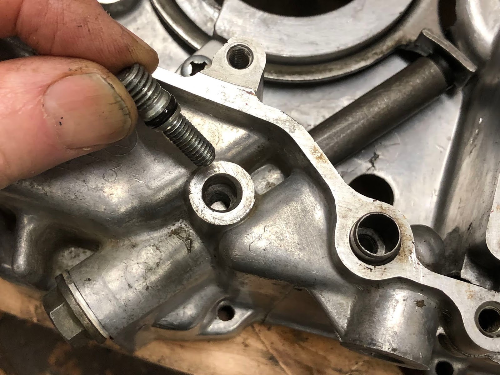
While I won't mention it at each step in the assembly process, its always a good habit to check all the oil passageways while you are assembling each part of the engine to double check that they are free and clear. With the oil pump assembly there is the one hex bolt that has its center drilled out and one hole drilled in the side that I always double check to make sure it is clean and open by shining a flashlight in the side hole and making sure I see light when I look down the hole bored down the center of the bolt like in the picture below.

While its not always obvious there is an aluminum crush washer that goes underneath the drilled hex bolt and acts as a seal for the head of the bolt. Most of the time this crush washer is "stuck" to the oil pump housing and not really noticed. It's important not to loose this crush washer, so if it does separate from the housing during cleaning make sure to hang on to it and install it under the bolt during assembly.

Getting back to assembling the CT90's oil pump start with the base gasket.

next set on the oil pump housing.

Then drop in the small shaft that has a flat on one end that will drive the pump.

Then drop in the two components that are the actual oil pump.


Add the next gasket.

Then add the final cover and the fasteners.


Then tighten the fasteners down being careful not to over torque the hollow bolt and to have also installed the aluminum crush washer if it was loose from the pump housing.


For the next part of the assembly process I work on installing some components on the left housing. I start by installing the seal that will seal on the shoulder of the drive sprocket.

I'll first set the seat in the bore where it will be installed.

Then I'll use something like a block of wood and gently tap it into place until it is flush with the rim of the bore I am installing it into.

Next I'll work on installing the parts that make up the timing chain tensioning system.

The first step is to set in place the assembly that has the roller that rides on the timing chain and the tab that engages the spring loaded plunger that generates the force that tensions the timing chain.

The ring is captured buy three metal tabs two of which are identical and one that is unique. The unique tab that has a small feature/key is installed at the position near and underneath the roller, with the small key like feature engaged in the mating slot in the housing that will keep it from rotating.

The other two tabs are installed in the remaining positions with the curved edge of the tab facing down so the it will keep the tab from rotating when it is in its final installed position.

The next step is to install the spring and plunger components that provide the force to tension the timing chain. The parts that make up this assembly can vary between different years of CT90 engines, but the one I am installing here is the simplest configuration.

The installation of these components it pretty straight forward and is shown in the series of pictures below.


Here is a picture of the left side case with theses sub assemblies installed. At this point I'll check that the timing chain tensioning ring can rotate against the spring loaded piston.

There are actually a few different configurations of plunger assemblies used in the cam chain tensioning assembly on CT90's. I thought I would include the series of photos below on the plunger assembly from a 1972 CT90 I am currently rebuilding since this is a common configuration on many later CT90's.
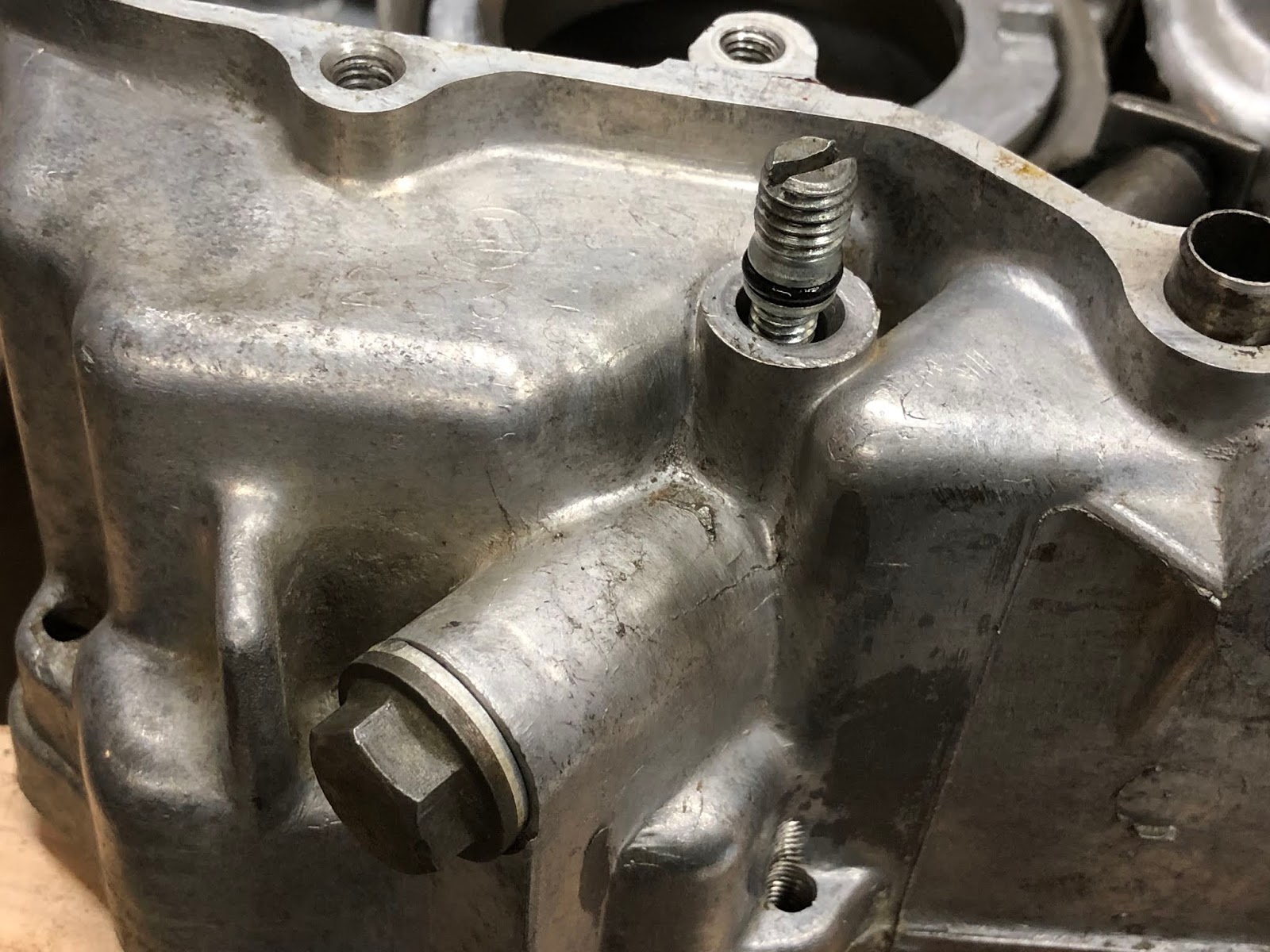
Here are the components associated with the plunger assembly and this has the added feature in that the spring force is adjustable to account for any stretch in the cam chain over time.
The first step is to insert the softer spring into the bore of the plunger and then insert that assembly into the opening in the housing with the tampered flat on the plunger facing upwards as shown in the pictures below.

Next insert the stiffer spring into the bore of the plunger and then to push the plunger up all the way until it contacts the tab on the tensioning assembly. Then take the threaded plug and use it to compress the stiffer spring while you screw it into the housing as shown in the pictures below.


Continue to screw in the threaded adjusting plug until it is in far enough so that the threaded cap and aluminum sealing crush washer can be installed.
The last step is to install the threaded stud and lock nut that is used to lock the plunger down once it has been adjusted. It is important to make sure the o-ring is installed on the stud prior to its installation.


Once you have your CT90 up and running you will need to come back and do an initial adjustment with this cam chain tensioning system. If you go to the following link here and scroll down about a third of the way you will reach a section titled Cam Chain and this has the basic procedure you need to follow to adjust the cam chain tensioner with this type of configuration.
Getting back to assembling the 1971 CT90 engine...
The next step of the process is to build up the sub assemblies that make up the transmission. I'll first build up the shifting fork assembly that includes the parts in the picture below. You might not bother to disassemble these parts if you were rebuilding your CT90's engine, but I did it here because I was really trying to get all the internal parts clean.

The first step is to install the copper sheet metal part that is what actuates your neutral switch.

To install this part you slip it over the short shaft one the one end of the shifting drum and then carefully insert the hooked tab into the hole it mates too.


The next step is to install the two shifting forks onto the drum.

The two shifting forks are slightly different and the one with the smaller fork being installed on the end of the shifting drum with the short shaft and the other with the larger fork being installed from the other end of the shifting drum.
Each of the shifting forks has a hole near the base of the fork that you will install a grooved pin. To install the shifting fork slide it on the correct end of the shifting drum until the hole is lined up with the waves groove that runs around that end of the drum.

Once the hole is lined up with the correct groove drop one of the pins in with the groove facing up. A small magnet is helpful when you are trying to remove these pins.

Once the pin is fully inserted (it will be flush with the top of the hole you are inserting it into) then take one of the small wire spring clips and slide it in through the two small holes on the face of the fork as shown in the picture below to lock the pin in place.

After you complete the installation of the one shifting fork repeat the installation process with the other shifting fork.
The next step is to assemble the gears and shafts that make up the transmission and are shown in the picture below.

These parts are assembled by sliding them on to the shaft in the order shown in the photo above and the end result is shown in the photo below.

One important detail that is not shown in the above picture is that the last gear installed on the smaller shaft assembly has both a solid face and a pocketed face. The pocked face should be installed facing the pins on the gear that was installed first on the smaller shaft.
The next step is to mate the shift fork/drum assembly to the transmission gear shaft assemblies. with the shifting forks engaging the sliding gear of each of the shaft assemblies as shown in the picture below. The smaller shaft assembly was flipped in the picture below so that it would correctly mate with the shift fork/drum assembly.

The washer shown in the above photo is a thrust washer that will be installed on the end of the larger gear shaft that it is next to in a later step.
In the next step of the assembly process we will install the transmission gear assembly we just finished putting together into the left engine housing that we earlier installed the timing chain tensioning assembly into. To prepare for the installation of the transmission gears first take the left engine housing and set it on your wood engine stand with the timing chain tensioning components facing down.
Next fold/rotate the two transmission gear shaft assemblies towards each other while keeping the shifting forks engaged so that you have an assembly like is shown below setting in the palm of your hand.

Next take the assembly that is in your hand and insert the long larger shaft through the ball bearing in the left engine housing and slide down the complete assembly until the short shafts on the end of the smaller gear shaft and shifting drum are seated in their respective bores in the left engine housing as shown in the pictures below.


In order to secure the gear assembly we just installed into the housing we need to install a special bolt and washer into the threaded hole of the shifting drum as shown in the pictures below. You'll need to lift up the housing from the engine stand to install this bolt and I will usually put a drop or two of blue loctite on the threads of the bolt.


With the left engine housing setting back down on our wood engine stand, our next step is to install the crank and main bearing assembly. With the crank assembly in the orientation shown in the picture below lower it down so the main bearing engages the bearing bore in the housing.

If the crank assembly doesn't drop immediately into the bearing bore it is ok to take a plastic mallet and very lightly tap on the shaft or around the crank until finally drops into place.

The next step is to now take the thrust washer I mentioned earlier that goes with the larger shaft of the transmission assembly, and install it on the end of the shaft as shown in the picture below so that it is resting in the end of the large gear on that shaft.


To finish off the engine housing, I install the main gasket. There is a small section of the gasket that goes across the opening for the piston rod that can either be removed now or later.


The spring just slips over the end of the shaft and the shorter hook engages a mating feature on the arm on the shaft as shown in the picture below.

That assembly is then installed from the inside of the right engine housing through the appropriate hole as shown in the picture below.

The kickstarter shaft assembly is slid all the way into the housing and the closed loop portion of the spring is mated into the cast feature of the housing as shown in the picture below.

The next step is to engage the remaining hooked end of the spring into the opening in the casting as shown in the picture below.

The last step is to pull the shaft back out just far enough so the the arm the the short hook is mated too can be rotated clockwise (which winds up the spring) until it is past the blocky stop feature of the housing and then the shaft assembly is pushed all the way back into the housing until it is seated.

I made the following short video to show the basic function of the kickstarter shaft and gear.
With both of the engine cases complete to this point its time to assemble them together.

With the left engine case setting in the wood assembly tool, lower the right case down over the various shafts until the to housings are together.

With the two housings together, the next step is to install the screws that will finalize the assembly. I am using socket head screws and I always apply an anti-seize compound when installing steel screws in an aluminum housing. I strongly recommend the use of socket head screws as it makes any disassembly in the future much easier.

Then torque down the screws to the appropriate torque value.

The next step is to install the shift drum stopper pins and plate.

The first step is to simply insert one of the pins in each of the four holes in the end of the shifting drum.

With all of the pins installed one of them will be proud or sticking out slightly and that is what is used to clock the plate to the drum.


The next step is to install the screw that holds the plate to the drum and I will always use "blue" loctite on this screw to help prevent it from coming loose.

The next step is to install the shifting linkage and shift drum stopper components.

To begin the process slide the shaft through the linkage arm and then insert the shaft through the appropriate hole in the housing as shown in the picture below

Next, without the shaft fully inserted into the housing lower the linkage arm all the way down so that the two legs of the spring engage the post in the housing and then with your finger rotate counterclockwise the smaller spring loaded arm that will engage with the groove and pins of the shifter drum.

Once clear of the shifter drum lower the arm the remaining distance and then let go of the smaller spring loaded arm so that it engages the groove in the shifter drum like is shown in the picture below.

The next step is to slide the shaft the remaining distance into the housing until the notches on the bent arm on the shaft engages the two legs of the spring that was part of the linkage assembly.


The next step is to install the shift drum stopper. First install the small coil spring over the raised boss in the housing.

Next take the special bolt and make sure the shoulder on the bolt mates with the hole on the shift drum stopper.


Next install the shift drum stopper by hooking the coil spring into the detent on the arm and then tightening the bolt down into the boss. I also use "blue" loctite on this fastener. The final installation should look like the picture below.

The next step is to the drive gear and main shaft spacer and bushings shown in the picture below.

Install the spacer on the main shaft.

Followed by the bushing.


Next install the drive gear on the splined transmission shaft and secure with the retaining ring.


The next step would be to build up the clutch pack, and while I won't go into that detail here I did do a detailed post on how to assemble the clutch pack here at this link. With a fully assembled clutch pack slide it down on the main shaft until it is fully engaged with the drive gear and seated against the spacer installed earlier.


The next step is to install the hardware that retains the clutch pack to the main shaft and the cover and bearing that mount to the clutch pack.

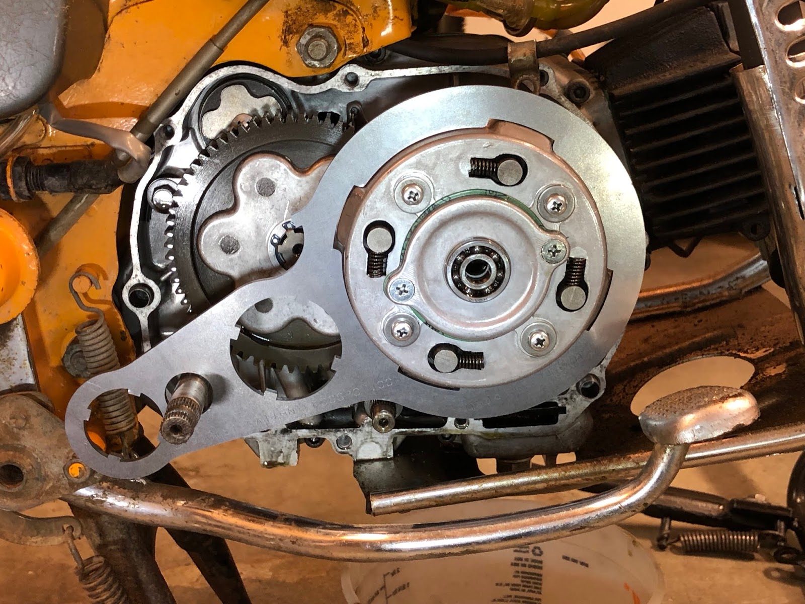
Looking down on the clutch pack the first step is to drop in the lock washer.

The three tabs on the ID of the lock washer actually are meant to engage the splines on the ID of the clutch pack and the lock washer should be sitting flat if it is installed correctly.

The next step is to install the spanner nut by threading it down onto the main shaft until it contacts the lock washer.

Using a suitable tool to keep the clutch pack from rotating and a spanner wrench attached to a torque wrench, tighten down the spanner nut to the appropriate torque.


The clutch pack holding tool I am using above is a little goofy but its cheap and it works. I did a post on making your own at a link here.
I also now sell the clutch holding tool in the picture below that I designed and that can also be used to loosen the headset nuts on most Honda CT90's. Here is a link to the post I did that includes a link to where I sell the tool on eBay.
Once the spanner nut has been tightened to the appropriate torque value you need to check that one of the four slots on the nut is lined up with one of the six tabs on the lock washer. If none of the slots are lined up with a tab you need to rotate the nut slightly until one does like the ones at the one o'clock position in the picture below.

Once you have a tab and slot that line up take a blade screw driver and bend the tab into the slot like is shown in the picture below.

To install the cover and bearing, first place the gasket at the interface.

Next install the cover and two mounting screws.


The bearing simply drops into the bore on the cover that was just installed.


At this point in the assembly process its not a bad time to install the stator assembly on the left side of the motor while a clutch holding tool can still be used to hold the main shaft while the stator bolt is torque. For this example on how to reassemble a CT90 engine I am going to continue the remaining assembly work to close up this side of the engine.
The next step is to install part of the clutch release mechanism and the oil filter screen.

The clutch release mechanism is a lever/arm actuated ball ramp device. The first part to install is the ball ramp plate shown in the top of the above picture. The short post/shaft on the ball ramp plate is simple inserted into the ID of the bearing previously installed in the cover of the clutch pack as shown below.

The next parts to install are the plunger and spring where the spring is first installed into the end of the plunger and then that assembly is installed into the small bore at the center of the ball ramp plate previously installed.


Next the splined end of the lever/arm that actuates the clutch when you change gears is slid down on its mating shaft and the end of the arm/lever is mated with the radius notch in the ball ramp plate so the when finally installed the arm/lever points directly at the center of the clutch pack.


The next step is to install the spring on the ball ramp plate as shown in the picture below.

And then set the plate that contains three ball bearings on the ball ramp plate making sure to orient the curved side of the plate towards the arm/lever as shown in the picture below.

Next install the oil filter/screen by inserting the thin end in first and then fully seating the filter/screen so it is flush with the surface.


The next step is to install the gasket making sure that it is over the cylindrical dowels used to align the cover to the engine housing.

The next step is to assemble the parts that make up the right side cover assembly shown in the picture below.

The first step is to instal these for the kick starter shaft. Set the seal in the bore it will be installed into and then use something like a block of would to protect the seal and tap it into the bore with light taps with a hammer.


To fully seat the seal in the bore you can use a socket that is slightly smaller then the bore diameter in place of the block of wood and then continue to tap with a hammer until fully seated.


The next step is to assemble the parts that make up the clutch adjustment mechanism. Take the component that is threaded on both ends and screw the larger threaded end into the ball ramp plate starting from the side with the fixed pin. Screw this part in until it is lightly seated.


Next take this assembly and inset it into the right side cover as shown in the pictures below.


Next take the cupped components that contains a small integral seal and assemble it of the threaded stud in the housing and then secure with the remaining nut, leaving the nut only hand tight at this point.


The right side cover assembly is now complete.

Next install the cover on the right side of the engine buy lowering it into place.


Next install the screws into the cover and torque to the appropriate value. Again, I recommend using socket head screws and applying anti-seize compound to the threads.

With the cover installed and before moving the engine, you should go through the clutch adjustment procedure called out in the Honda manual so the all of the ball ramp components within the clutch mechanism are in their correct position.
This is also a good time to install the drain plug into the bottom of the engine.


It is now time to flip the engine over so that we can complete the assembly of the left side of the engine.

The first items we will install on the left side of the engine are the timing chain and the gear/shaft assembly that is driven by the timing chain and drives the oil pump.

To install the gear that drives the oil pump I first apply some assembly lube or oil to the journals on the shaft and then insert into the appropriate bore and the rotate it until it engages the tab on the oil pump. The gear is properly installed and seated when it is in line with the roller that is part of the timing chain tensioning system.


Next install the timing chain by inserting it through the opening on the side of the left engine case and routing it around the drive gear on the main shaft. At this point the timing chain is only partially installed and you need to be carful not to damage the chain while you assemble the rest of the engine.

The next step is to install the generator and neutral switch components.

The first step I do is to install the generator rotor by lining up the slot/keyway in the generator rotor with the key in the tapered main shaft and then lower it into position.


Next install the bolt and washer that hold on the generator rotor and torque to the appropriate value.

The next step is to install the generator stator and neutral switch. There are several things going on here in this step, but you get the stator in features that cradle it in the housing while also starting to guide in the molded rubber wiring elements into their respective features in the left side case while also insert the neutral switch into its respective bore.

Once everything is located slide each element down into their final positions.

The following picture is a detail of the machined recess that the generator stator rests in when it is installed properly. Install the screws into the generator stator and tighten.

There is a small plastic "C" shaped collar that is installed over the neutral switch and is needed to capture the switch once the left side cover is installed.


If your small "C" shaped collar that goes over the neutral switch has broken or is lost I have provided the dimensions below in case you need to make one as they are a very simple part to make.
Outside Diameter = 0.636 inches
Inside Diameter = 0.317 inches
Height = 0.354 inches
Slot Width = 0.190 inches

I also thought I would include a detail photo of how the neutral switch is attached to the wire from the wire bundle. The neutral switch has a hole through the end of the post at the end of the switch. To attach the tinned wire from the wire bundle a spring loaded washer at the end of the switch is pulled back, the wire is inserted through the hole and then the washer is released and holds the wire in place.


Here is a picture of the generator stator and the neutral switch in their final installed positions.

The next step is to build up the left side cover and then install the forward drive sprocket and cover on the left side of the engine.

The first step in building up the left side cover is to install the gear shift shaft seal. Because the cover has alignment pins you should support the cover on two blocks or other suitable surfaces so the is no risk of bending the cover while installing the seal.

Place the seal in the bore and then use a block of wood and/or a similarly size socket and tap the seal into place so that it is fully seated in the bore.


The next seal we will install is for the forward drive sprocket and it installs from the other side of the cover.


Using a wood block or other suitable material tab the seal into place until it is flush with the surface.

Here is the cover with both seals installed.

Next install the forward drive sprocket buy applying a little oil to the surfaces that will engage the ears in the housings and then lower it down over the splined shaft and work it into the seal on the engine housing.


To install the cover first install the gasket on the left side of the engine assembly.

Next lower the left side cover down over the gear change shaft and the forward drive sprocket until it is fully seated against the engine housing.


Next install the screws that retain the cover and torque to the appropriate value. Again I recommend using socket head screws and applying anti-seize compound to the threads before installing.

The next step is to assemble the sub-transmission. I have done a previous post where I go into significant detail on building up the sub-transmission and it is available here at this link. The following is a picture of the components that go into the sub-transmission assembly.

The first step is to install the lever that allows you to change between high and low range. Make sure the o-ring is in the groove and then apply a little grease to the shaft an orange and fully insert it into the bore in the side case.

Next install the forked gear change lever plate over the end of the shaft of the lever that was just installed and make sure the groove for the retention clip is visible.

Rotate the lever towards the rear of the engine.

And install the clip as shown below.

Next take the large gear with the three dogs facing up and slip it over the splined shaft and drop it down so it is fully seated and engaged with the larger splined shaft.


Next take the large flat washer that is splined in the ID and drop it over the splined shaft so that it is now resting on the gear that was just installed.


Next install the external snap ring that will lock these parts in place.


The next step will be to assemble the smaller gear that is splined on its ID to the shifting fork assembly as shown below.

The next step will be to assemble the long shaft with a pin on one end into the double gear as shown below.

For clarity, the picture below shows how the pinned end of the long shaft engages the bore and keying slot in the left side cover when the the combined assembly of the double gear and shaft are finally installed.

Next move the high/low range selector lever towards the front of the engine so that the fork on the lever is pointing out and then take the two gear assemblies and mesh them together and lower them down into the housing as shown in the picture below.

Once everything is fully seated move the high/low range selector lever back and forth to verify that the gears will move between the hi and low range positions.
This is the high range position

And this is the low range position

The next step is to install the gasket on the housing.

And then install the bearing by slipping it into the bore of the cover.

Then set the cover on the housing

Install the screws and torque to the appropriate value. Depending on your engine, your cover may have one or two guide dowels to align the cover to the left side case. Again I recommend that you use socket head screws and anti-seize compound on the threads.

Next we will install the piston and cylinder and here are the majority of the parts used in this next step.

We'll start with installing the rings on the piston. I am not going to go into any detail about checking the end gap of the rings, etc. as I have never really bothered to check that on any bike or car piston I have installed over the last 45+ years and have never had a problem. Maybe I'm just lucky, but I think it is more that any automotive or motorcycle manufacture could never afford the time required to do that sort of check in a production environment and the focus is more on holding manufacturing tolerances tight so it won't be an issue. I have also found that the CT90 cylinders I get back from DrATV are always on the larger side, so I have never worried about it.
I am also not going to try and explain in detail how to install each ring as there is a feel to it, so I'll just say that if you haven't done it before take your time and try not to break the compression and scraper rings as they are brittle. If you do end up breaking a ring well welcome to the club and now you with hopefully have the experience that you won't do it again with the next set of rings you have to buy.
There are there rings that need to be installed.
The top ring is the compression ring.
The next ring down is the oil scraper ring
And the bottom ring is actually an assembly of three rings and is call the oil ring.

For the compression and oil scraper ring they have a top side that must always be installed up with respect to the top of the piston. To help make it easy to identify the top side of the ring both the compression and oil scraper are marked in a manner like what is shown in the picture below, but will vary between ring manufactures.

The first ring we will install is the group of rings that makes up the oil ring.

You first install the larger corrugated ring that is gold colored in the picture above into the bottom groove and make sure the two ends of the groove butt up against one another and don't overlap. Next you would take one of the remaining two thin rings and install it around the base of the corrugated ring just installed. Next take the other thing ring and install it around the top of the corrugated ring making sure to have the gap of the ring not aligned with the first thing ring installed and preferably 180 degrees out from the gap on the lower thin ring. Once all of the components that make up the oil ring are installed it should look like the picture below.


Now that the oil scraper ring is in the second groove repeat the process with the compression ring making sure the markings are facing up.

If you installed all three rings correctly it should look something like the picture below. When you actually go to install the piston in the cylinder you will want to make sure the gaps between all the rings are approximately 120 degrees apart and I prefer to have those gaps on either the left or right side of the piston and not directly on the top or bottom of the piston. Having the gaps staggered helps create a labyrinth seal for any gas that escape through the first gap in the compression ring.

The next step is to install the piston on the piston rod using the wrist pin and two retaining rings.

Before I install the piston on the piston rod I will install one of the wrist pint retaining rings in the groove at one end of the bore for the wrist pin.

The next step is to first make sure the "intake" depression the top of the piston is facing up and then place the piston over the end of the piston rod until the bore at the end of the piston rod is aligned with the bore for the wrist pin in the piston.


Once they are aligned then lube the wrist pin and the bore for the wrist pin with assembly lube and insert the wrist pin until it is fully seated against the retaining ring we installed earlier.


With the wrist pin fully seated now install the remaining retaining ring in the groove in the wrist pin bore of the piston.

The next step is to install the cylinder on to the engine. During this step I also apply assembly lube to the piston and cylinder to make sure there is some lubrication during the first operation of the engine.

Before installing the cylinder you need to first install the gasket that goes underneath the cylinder and also the rubber seal that goes in the groove around the opening for the timing chain.

To install the cylinder slide it down over the four studs until your reach the piston.

Once you reach the fun begins. With a stock cylinder bore the base of the cylinder has a nice large chamfer that really helps with getting the rings started. If you have a small piston ring compressor you can use it, but I have always just compressed the rings with my fingers while working the piston into the cylinder bore.

One downside of the DrATV Big Bore is that a large amount of the lead in chamfer is machined away due to the larger bore diameter so there is less of a chamfer to help with the installation of the rings. The process I use is to first insert the bottom of the piston and first ring in a little ways into the chamfer and then use my fingers to squeeze the ring in the area of the two cut outs that exist on each side at the base of the cylinder until I can work the top edge of the piston and first ring into the bore of the cylinder.

I keep repeating this process until all the rings on the piston are in the bore of the cylinder.

Before you can complete the installation of the cylinder you need to feed the timing chain through the opening in the cylinder with a focus on trying to keep a little tension on the timing chain so it stays engaged on the gear on the main shaft of the crank.

With the timing chain routed through the opening in the cylinder slide the cylinder down into its final position.

The next step is to install the timing chain idler wheel.

To install the idler wheel position the idler wheel under the upper strand of the timing chain and then move it in through the opening in the cylinder casting until the center of the wheel is aligned with the threaded hole in the side of the casting.

With the idler wheel aligned install the bolt through the washer and into the threaded hole so the idler wheel is now riding on the shaft that is the end of the bolt you just installed.

The idler wheel is designed to float on the bolt/shaft so that it is always inline with the timing chain. The aluminum washer under the bolt is soft so that it can be an oil tight seal at that interface.

The next step is to build up the cylinder head assembly by first installing the valves. I am not going to go into any detail on preparing the valves and valves seats and only focus on installing the physical components. If you do need a set of valves I have used a set of Shindy 07-002 valves that are available at this link here at Amazon.

We will first install the exhaust valve by applying assembly lube to the stem of the valve and then full insert the exhaust valve from the combustion chamber.

Flipping the cylinder head over we will install the remaining exhaust valve components at the end of the valve stem and the fist component to be installed is the thin steel washer that will be the seat for the larger valve spring.

The next parts to install are the two components that make up the exhaust valve stem seal.

You first install the small seal with the seal lip facing up and slide it down the stem of the exhaust valve until it is seated as shown in the picture below.

Next slide down the top hat looking component that will retain the exhaust stem seal until it is fully seated and a the small lip of the seal can bee seen protruding from the top.

Next install the smaller diameter inner exhaust valve spring.

And then the larger diameter outer exhaust valve spring.

The next step is to install the remaining components at the end of the valve stem that will finish off the exhaust valve installation.

First we will install the cupped washer that will lock in the valve stem retaining clips by setting it over the end of the stem of the exhaust valve.


You will need a valve spring compressor to complete the next step. I use a simple tool that I made that utilizes a C Clamp that does the job. I made a post on the method and tool I use at the following link.

With your valve spring compressor in place, compress the valve springs until the end of the valve stem is slightly above the cupped washer.


Next position the two valve stem retaining clips in the cupped washer so that the lower edge of the retainers are under the machined rim at the end of the valve stem.

Uncompress the valve spring and remove your valve spring compressor and the installation of the exhaust valve is complete.
If you are not familiar with the small retainers used at the end of the valve stem here is a couple of pictures of the retainer and how it mates to the end of a valve stem.


Follow the same process to install the intake valve. The only difference from the exhaust valve installation is that on my 1971 CT90 there was not a seal on the valve stem.
First, after applying assembly lube to the valve stem, install the intake valve into the cylinder head coming in from the combustion chamber.


Next install the thin steel washer that will be the seat for the larger valve spring.

Then install both the smaller diameter and larger diameter valve springs.


Then the cupped washer.

And then use your valve spring compressor to compress the springs and install the valve stem retainers.

Another option for a valve spring compression tool is the one made by Hardy Tool and Mfg. as shown in the following video link. I think this tool has been available on eBay, but it is a nice simple design, so if you do come across one it would be something worthwhile picking up.
With the installation of the valves complete we can now install the cylinder head and the components needed to complete the installation of the timing chain.

To start the cylinder head installation we must first position the crank so that the mark for "Top Dead Center" on the generator rotor is aligned with the pointer as shown below. I also did a related post where I go into significant detail on how to set you timing at this link that has additional information that might be useful at this step in the process.

Next you need to take the timing chain gear that will attach to the camshaft and mate it to the timing chain so that the "O" stamped into the gear is facing out and pointing away from the engine. Also, the two threaded holes in the gear must be directly in-line with the center of the bolt for the idler wheel we installed earlier and should look like the pictures below.


The next step is to install the two oil seals that will go between the cylinder head and the cylinder. The first is a formed rubber seal that fits into the opening around the timing chain.

The second seal is a small cylindrical rubber ring that goes over a short steel tube that is shown in the picture below.

This is slipped over the lower right cylinder head stud.

And slid down until it is mated into a small counter bore in the cylinder.

The last component to be installed on the cylinder head before it is installed on the engine is the head gasket (this head gasket is actually not the correct head gasket for my big bore kit and I changed it out before installing the head...).

To help keep the head gasket in place while the cylinder head is installed I'll put a very small amount of assembly lube on the back side of the gasket which helps it stick to the cylinder head during installation.


The next step can be a little tricky, but while holding the gear and timing chain taught slide the cylinder head down over the studs and slowly work the gear and timing chain up into the opening in the cylinder head as you move the cylinder head down and finally seat it against the cylinder.


Next take the cam that you pre lubed with assembly lube on the lobes and bearing journals and insert it through the hole in the timing gear and into the cylinder head. In order to get the cam all the way inserted you may have to temporally install the cover and cylinder head stud nuts to compress the cylinder head and cylinder against all the seals so that the hole in the timing gear lines up with the bore in the cylinder head.

With the cam fully inserted into the cylinder head and through the timing gear, make sure the crank is still positioned at the top dead center mark.

And then verify that the "O" on the timing gear is aligned with the notch in the cylinder head housing as shown in the picture below.

Next rotate the cam so that the pin on the shaft of the cam points toward the "O" and the notch in the cylinder head. At this point the holes in the flange of the cam should line up with the threaded holes in the timing gear.

Install the two short bolts that attach the cam to the timing gear (no picture provided).
If you had installed the cover and cylinder head stud nuts earlier you will now need to remove them to complete the next step.
The next step will be to finish the installation of the cylinder head by installing the valve rocker arms and the associated covers.

Before I install each of valve the rocker arms I'll first back off the nut and stud at the end of the rocker to about its mid position so it will be easier to install the rocker arm. I'll also apply assembly lube to all the moving surfaces of the rocker arms and the pins/shafts they ride on before installing the parts.

I'll generally install the rocker arm for the intake valve first and once it is in position slide in the shaft that it will ride on into the bore on the side of the cylinder head.


At this point there should be significant play between the adjustment stud at the end of the rocker arm and the top of the valve stem. We will adjust this gap at a later step of the assembly process.
To install the rocker arm on the exhaust valve you basically follow the same process, but there is else room in the cylinder head with the intake rocker arm installed, so you have to manipulate the exhaust rocker arm a little bit to get it into position so that you can install the shaft for the rocker arm. Sometimes the rocker arm drops right into place and other times its been like a Chinese puzzle. I have included a short video below to show the method I use that usually works to install the exhaust rocker arm.
With both rocker arms and shafts installed we are ready to install the cover on the right side of the cylinder head.

With the gasket in place install the cover and tighten down the three screws that retain the cover.


The next step is to install the cover at the top of the cylinder head and we start by first making sure the gasket is in place.

Then the cover.

And finally the washers and nuts that will be used to secure the cover and the cylinder head to the engine.

When installing the washers and nuts in this step it is important to make sure and use the copper washer and acorn nut on the lower right stud. The copper washer and acorn nut are used at this position to provide an oil seal for the pressurized oil coming up to the top of the cylinder head along this stud.
Once all of the washers and nuts are installed, tighten the nuts to the torque specified in the Honda manual using a criss cross pattern while tightening the nuts. I'll generally recheck the torque on these nuts after a couple of hours to account for any compression that may have occurred in the gaskets.
The next step of the process is to adjust the gap between the stud on each rocker arm and the top of the valve stem. You first need to make sure that the crank is positioned at top dead center as shown earlier. The next step is to screw down each adjustment step until it contacts the top of the valve stem and then back it off so there is a gap of .002 inches (Refer to the Honda manual) and then while holding the stud at the .002 inch gap, tighten down the lock nut.
If you don't happen to have feeler gauges to use while adjusting the gap on the rocker arms here is a quick and dirty approach that I have been using for awhile now. Based on the thread pitch of the adjusting stud on the rocker arm an 1/8 of a turn on the stud is approximately .0025 inches, so most of the time when I am adjusting the valves on one of my CT90's I just screw the stud down until I contact the valve stem then back is off slightly less then an 1/8 of a turn and then lock everything down.
Once the valves have been adjusted the next step is to install the valve caps.

First place the o-ring seal on each of the caps.

And then install each cap in their respective positions on the cylinder head.

The next step is to install the cover on the left side of the cylinder head.

First install the seal in the bore at the center of the cover so that it is flush with the inner surface of he cover as shown in the photo below.

Next apply the seal to the interface for the cover on the left side of the cylinder head.

And then install the cover using the three screws and aluminum washers. The aluminum washers act as an oil seal as the get crushed slightly when you tighten the mounting screws. When you do install the cover you should apply some oil to the portion of the shaft next to the timing gear and to the lip of the seal and go easy and make sure not to roll the lip of the seal while installing the cover.

The next step is to install the spark advancer. Prior to installing the spark advancer you should make sure the whole assemble is clean and all of the components are free to rotate as intended. If you have taken apart your spark advancer to clean it (a good thing), but are not sure how it goes back together, I made another post at this link where I should how correctly reassemble your spark advancer.

To install the spark advancer simply slide it on to the shaft of the cam making sure the keyed slot on the advancer is lined up and engaged with the advancer when it is fully seated on the shaft.


Then install the retaining bolt and washer and tighten.

The next step is to install the plate and ignition points assembly.

Set the plate into the machined recess as shown in the picture below.

Make sure to install the rubber grommet on the ignition wire into the housing feature as shown below.

Then install the two screws and washers that retain the plate as shown in the picture below, but don't fully tighten just yet as we need to make a few adjustments.

The final step before we get into adjusting the points and setting the timing is to rout the ignition wire from the points up through the cast opening that has a small machined feature to allow clearance for the wire.


While I will go through the basic steps to adjust your points and set your timing here is this post, I would recommend you take a look at an earlier post I made here at this link where I go into more detail about this step in the assembly process. Also you will need a static timing light to complete the following steps and if you don't have one I made a post here at this link on how you can make your own from a basic LED flashlight.
In the next step we will set the gap in the points. To do this we start by putting a 14mm wrench on the head of the bolt that holds the generator rotor to the crank and slowly rotate the crank counterclockwise watching the points and we will stop the rotation at the point where the gap looks the greatest.

With a feeler gage check the gap and make sure it is within the range specified in the Honda manual. When I set my points I always use a .013 inch feeler gage and have found that gap to work well with all of my CT90's. If your gap is to big or to small you need to slightly loosen the two screws that attach the points assembly to the plate.

Then you need to insert a blade screw driver into the notch on the points and the two dimples on the plate and rotate the screw driver slightly in one direction or the other to open or close the points gap until the desired gap is obtained.


Once you have the desired gap tighten the two screws that hold the points assembly to the plate and then recheck the gap to make sure that the gap didn't change while you were tightening the screws. To double check I'll rotate the crank a couple of revolutions counterclockwise until I get to the largest gap and then recheck with a feeler gage to make sure the gap is correct.
With the point set to the correct gap we now will set the timing.
To set the timing we first need to hook up a static timing light with one lead going to the engine case and the other going to the free end of the ignition wire coming from the points. When the points are together the light should be on and when they are separated the static timing light should be off.
To verify that the timing is set correctly rotate the crank counter clockwise and before the line to the immediate left of the "F" mark stamped into the rotor of the generator reaches the pointer that is part of the generator stator, the timing light should be on.

Once the line next to the "F" mark just becomes in alignment with the line on the pointer the timing light should switch off.


If the timing light is switching off just before or just after the line to the left of the "F" mark reaches the pointer then you need to go back and loosen the two screws that keep the plate the points are mounted to from rotating and rotate the plate slightly counterclockwise or clockwise and repeat the process until the timing light changes state at the correct point.
Again I go into greater detail on adjusting your timing in my earlier post at the link here.
Once the timing has been set all there is left to do is install the two remaining side covers.

Starting with the cover the encloses the ignition points, first install the gasket for this cover and then the cover itself.

For the cover that provides access to the generator and timing marks install the gasket and then the cover making sure that the o-rings on each of the three screws that secure the cover are installed.

With the two cover installed the engine is complete and ready to be installed back into your CT90.

I'll install the oil cap/dipstick at this point, but I'll generally wait to put oil in a new engine until it is mounted back in the CT90, but you need to make sure you have filled the engine with the appropriate amount of oil before you start kicking over the engine for any reason. It's also not a bad time to install a spark plug and add some sort of plug to the opening for the intake manifold to prevent anything from dropping into the engine.
I hope you found this post useful and if you have been hesitating rebuilding your own CT90 engine, don't as it is actually a very simple and straight forward task that I personally also find very enjoyable.
Links to Related Posts:
Repairing Damaged CT90 Spark Plug Threads Using a Time-Sert Thread Insert
CT90 Clutch Pack Assembly Detail Build-up
Painting Honda CT90 Side Cases
Making a Low Cost Clutch Holding Tool for Your CT90
The Basic Sequence and Process to Set or Adjust your CT90 Timing
CT90 Sub-Transmission Reassembly
CT90 Spark Advancer Assembly Build-up
Helpful Links (Shop Manuals, Wire Diagram, Model Information, etc.)
Link to page with listing of CT90 parts available on Amazon
Thanks so much for this step by step information! What do you recommend for the engine brake in period? My son is almost done with his rebuild and did the same Dr. ATV big bore (53.5mm) piston.
ReplyDeleteHi, sorry for the delayed response. I don't have a specific recommendation and suggest that you do a search on the web and you'll find recommendations on specific methods you can follow to break in your new engine. For myself, I don't tend to follow a specific regimen when breaking in a new engine, but I do try and vary the load on the engine and avoid long sustained periods of running at a specific speed. After a few weeks I'll change the oil and call it good. This approach has served me well and while I'm sure there are people would love to debate what the best approach is, my general recommendation is to ride your bike, don't get crazy, and after a while change the oil and you should be fine as these are very forgiving engines.
Delete